
Method for tensioning boom and measuring tension, and device for method

A measuring method and technology of measuring device, which are applied in the directions of measuring device, measuring force, instrument, etc., can solve the problems of tension error, ambiguous constraints, complex parameters, etc., and achieve the effect of wide application field, accurate measurement, and favorable promotion.

Inactive Publication Date: 2012-07-04
JIANGSU UNIV OF SCI & TECH
View PDF4 Cites 13 Cited by
  • Summary
  • Abstract
  • Description
  • Claims
  • Application Information

AI Technical Summary

Problems solved by technology

The frequency method is to use the relationship between the tension of the tensioned boom and the natural frequency, and measure the natural frequency of the boom by the vibration testing equipment to calculate the corresponding tension. All the instruments in this method can be reused, so the frequency The method is currently the most economical and practical method, but the measurement accuracy of this method largely depends on the boundary constraints of the boom, the calculated length, bending stiffness, linear density and other parameters, in the ideal case of the above parameters can be To obtain better test accuracy, but in actual engineering, the constraints of the boom are very vague, and the calculation length and bending stiffness cannot be determined, and the above parameters will become more complicated after the damper is installed, which will lead to The tension calculated by the frequency method produces a large error, even wrong

Method used


Image

  • Method for tensioning boom and measuring tension, and device for method
  • Method for tensioning boom and measuring tension, and device for method
  • Method for tensioning boom and measuring tension, and device for method

Examples


Embodiment Construction

[0019] The present invention will be further described below in conjunction with the accompanying drawings and embodiments.

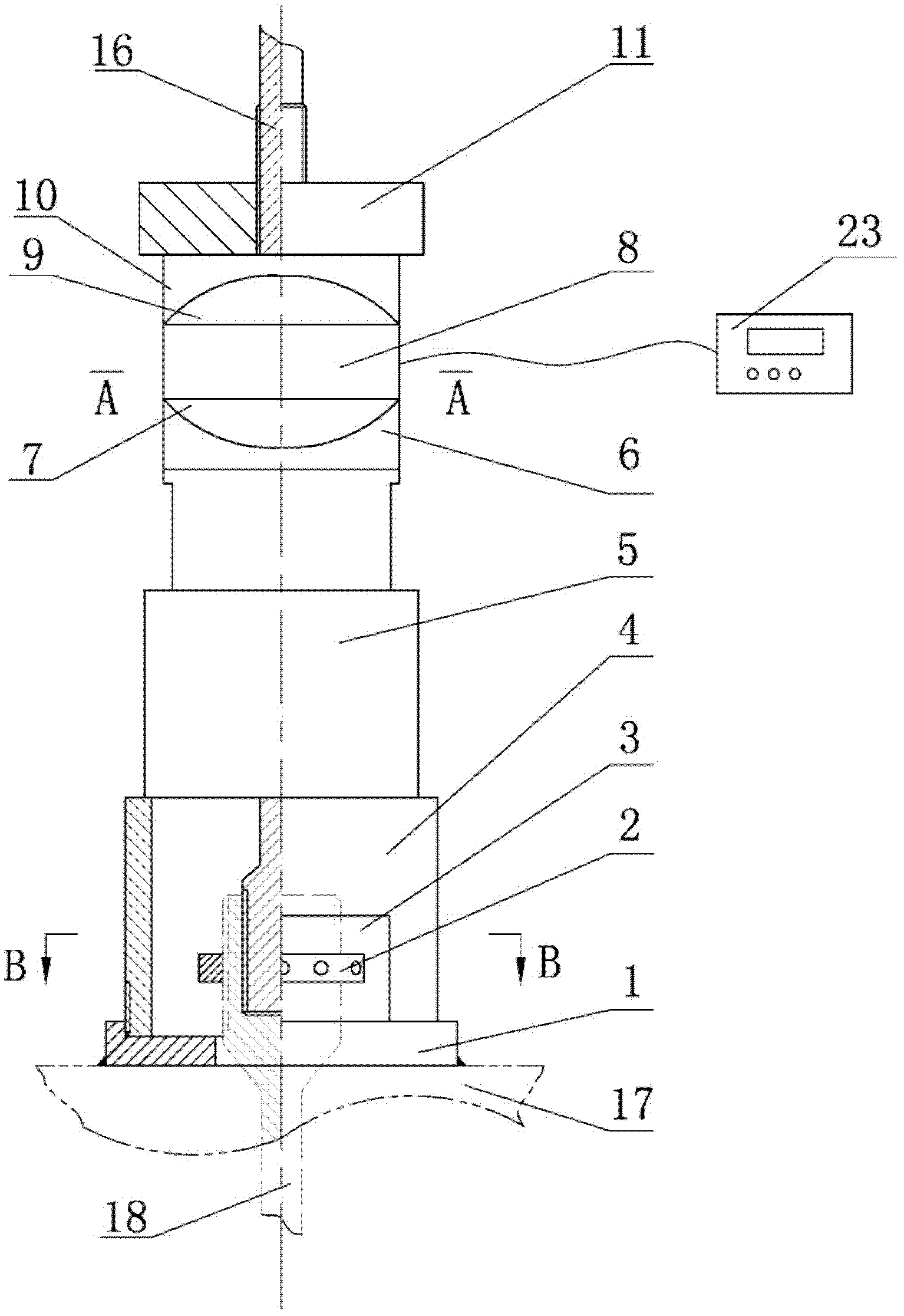
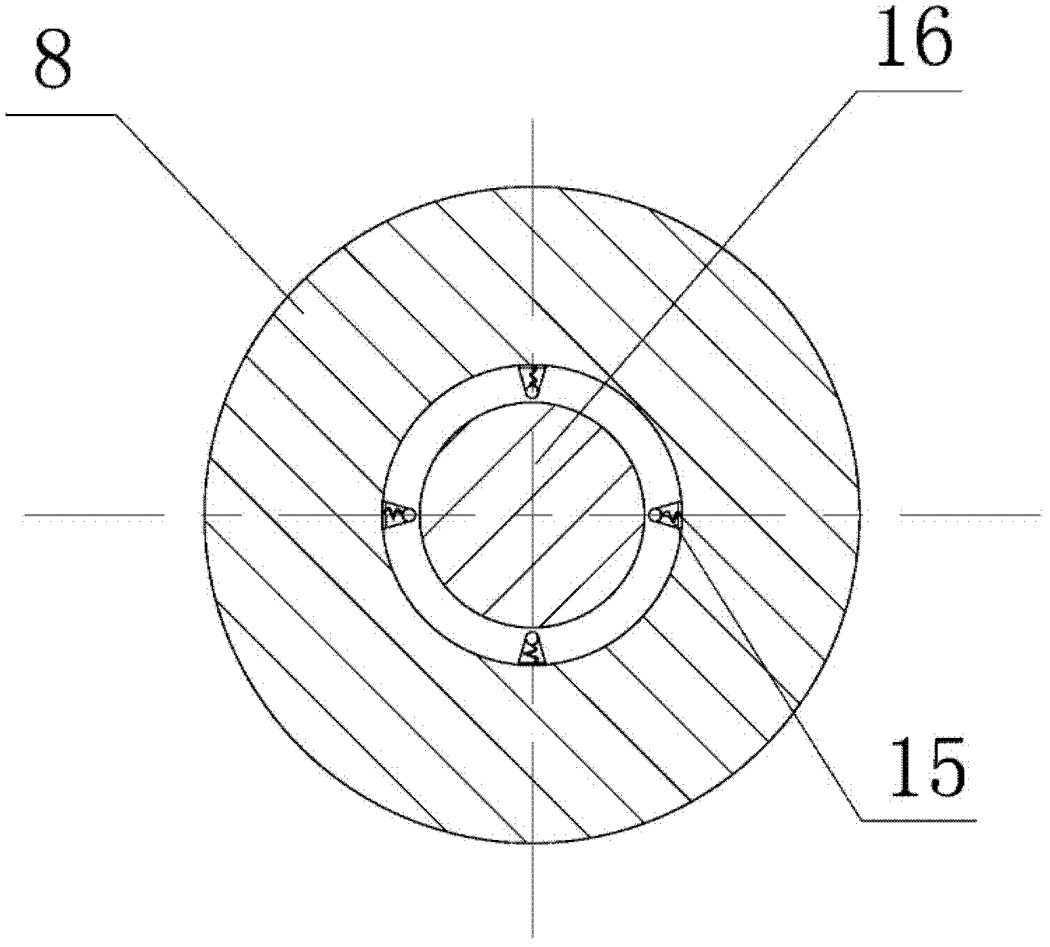
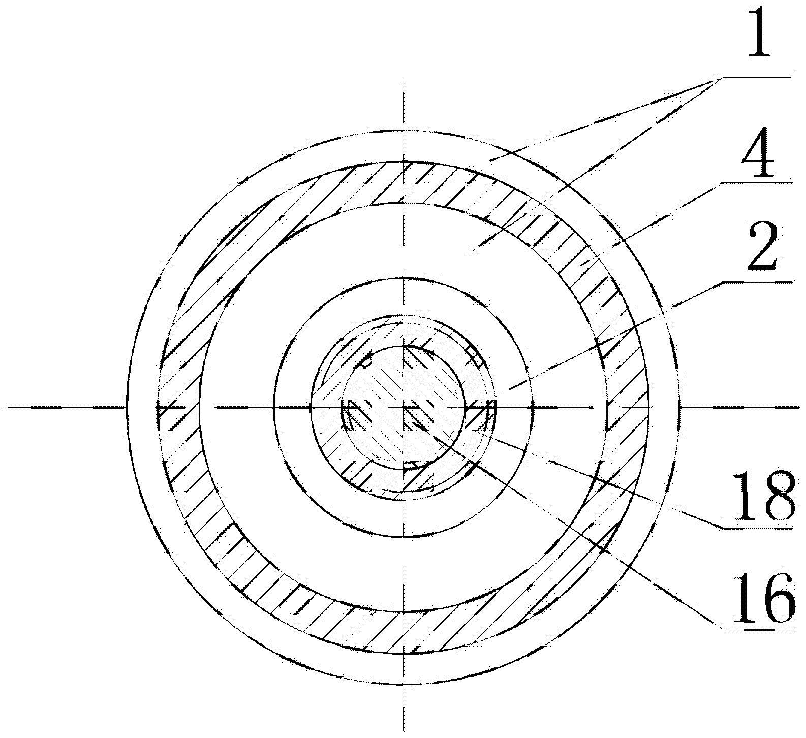
[0020] Such as figure 1 As shown, the measuring device of the boom tensioning and tension measuring method of the present invention consists of an anchor plate 1 with a central hole, a sleeve 4 with an adjustment window 3, a fixed nut 2, a through-hole jack 5, and a through-center force The sensor 8, the dynamometer 23, the limit nut 11, and the tension rod 16 are composed. The anchor pad 1 is welded and fixed on the upper end surface of the structure 17, and the lower end of the tension rod 16 is threadedly connected with the suspender 18 passing through the anchor pad 1. A fixing nut 2 for fixing the stressed state of the suspender is arranged on the outer periphery of the connecting end of the suspender 18 and the tension rod 16, and a sleeve 4 with an adjustment window 3 and a through-hole jack 5 are sequentially fitted along the tension pole 16 fro...


PUM

PropertyMeasurementUnit
diameteraaaaaaaaaa
diameteraaaaaaaaaa
elastic modulusaaaaaaaaaa

Abstract

The invention discloses a method and a device for accurately measuring a bridge boom and tensioning the boom. The device consists of an anchor backing plate with a central hole, a sleeve with an adjustment window, fixing nuts, a through lifting jack, a through force sensor, a dynamometer, a limit nut, and a tension rod; and the method comprises the following steps of: determining the through force sensor according to a Hooke's law and the maximum design tension of the boom, calculating the maximum stress of the tension rod, selecting the materials of a tension rod body according to the maximum stress, determining the lectotype of the through force sensor, sequentially assembling, and tensioning the boom by using the through lifting jack, reading the dynamometer, and displaying the force value of the through force sensor. The device has a simple structure, is high in accuracy and low in cost, and is detachable, and can be used repeatedly.

Description

technical field [0001] The invention belongs to the technical field of bridges, and relates to a measurement of bridges, more specifically, to a suspension rod stretching and tension measurement method and a device thereof. Background technique [0002] The tied arch bridge is a high-order super statically indeterminate structure. It combines the arch and the beam through the suspender to give full play to the structural performance and combined effect of the beam under bending and the arch under compression, and the horizontal thrust of the arch end is borne by the tie rod, so that Arch end bearings do not generate horizontal thrust. Therefore, the tension of the suspender is the core factor affecting the stress of the arch bridge structure, directly affects the rationality of the bridge stress, and thus affects the safety, service life and line shape of the bridge deck. Therefore, the tension control of suspenders is very important for tied arch bridges, and the tension o...

Claims


Application Information

Patent Timeline
Patent Type & Authority Applications(China)
IPC IPC(8): G01L1/00
Inventor 沈超明唐柏鉴李年维汪雅棋
Owner JIANGSU UNIV OF SCI & TECH
Learn More