Method and apparatus for laminography inspection

A detector, X-ray technology, used in instruments for radiological diagnosis, material analysis using radiation, material analysis using wave/particle radiation, etc., can solve problems such as reduced efficiency, high monetary cost, and complex gantry

Inactive Publication Date: 2012-07-04
GENERAL ELECTRIC CO
View PDF0 Cites 2 Cited by
  • Summary
  • Abstract
  • Description
  • Claims
  • Application Information

AI Technical Summary

Problems solved by technology

[0003] Unfortunately, the gantry associated with these single point x-ray sources is often complex and slow, reducing efficiency by increasing the amount of time required to accept or reject fabricated objects
Additionally, the complexity of such systems can lead to downtime associated with necessary repairs and breakdowns
Furthermore, such complex systems can be associated with high monetary costs and limited fields of view

Method used


Image

  • Method and apparatus for laminography inspection
  • Method and apparatus for laminography inspection
  • Method and apparatus for laminography inspection

Examples


Embodiment Construction

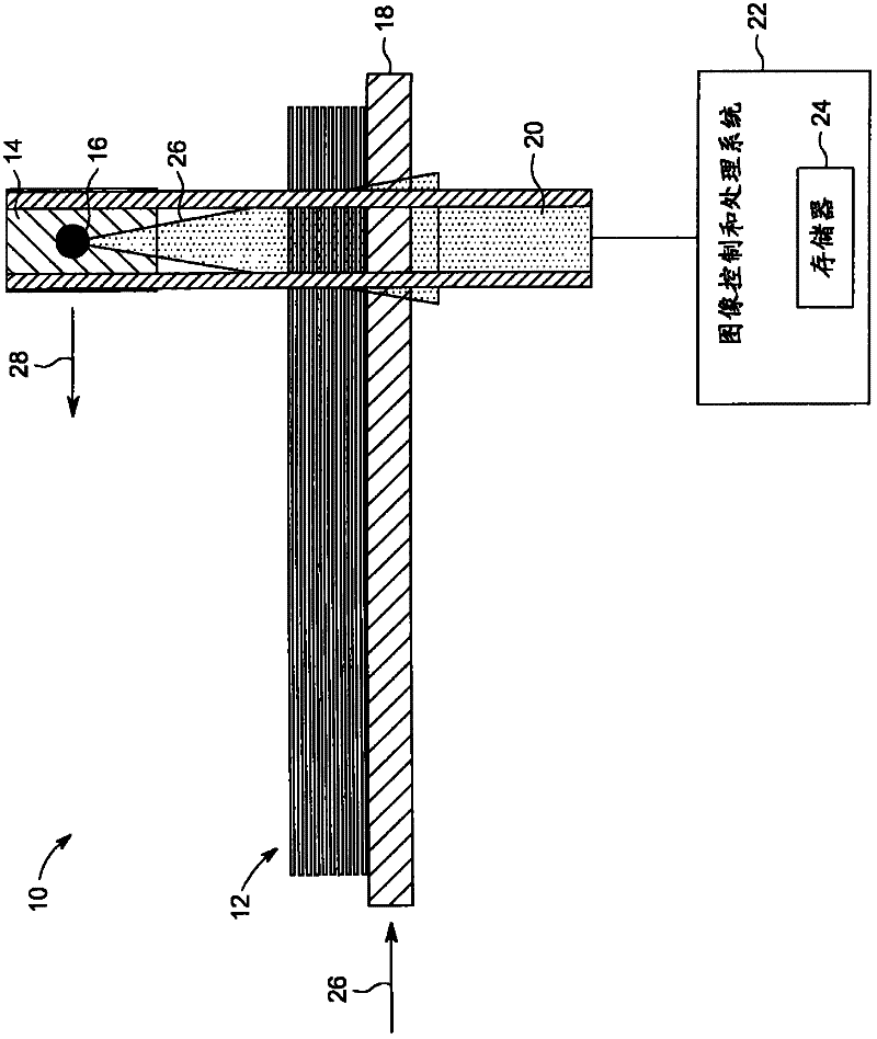
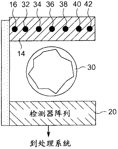
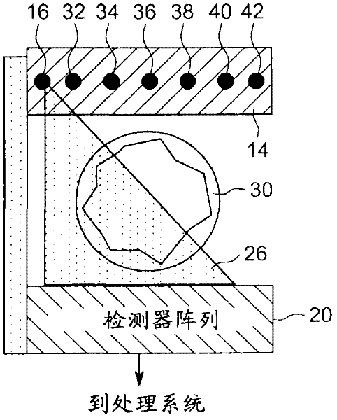
[0020] As described in detail below, embodiments of imaging systems are provided that include a substantially stationary multi-focus X-ray source that generates angularly displaced X-rays that illuminate an object prior to detection by a detector. Such systems are able to obtain a complete set of planar images of the object on an arc while remaining substantially fixed; this set of planar images can be used to reconstruct slices at different planes in the object. For example, in one embodiment, a processor of the laminar photographic inspection system may use the set of planar images to reconstruct a pipe slice, determine the wall thickness of the pipe, and determine the presence and location of defects in the pipe. Furthermore, in some embodiments, slices of an object (eg, pipe) can be reconstructed via a move-and-add step, and then mathematical deblurring techniques can be used to improve image quality and slice sensitivity curves.

[0021] The above-described features of em...


PUM


Abstract

Imaging systems including a multiple focal spot x-ray source adapted to irradiate an object with a series of angularly displaced x-ray beams, one at a time, without substantial rotation or translation of the multiple focal spot x-ray source are provided. Such systems also includes a detector adapted to receive at least a fraction of the angularly displaced x-ray beams after being attenuated by the object to produce at least two x-ray projection images of the object. The imaging systems also include a processor adapted to shift and add the at least two x-ray projection images to bring at least two planes of the object into focus, one at a time.

Description

technical field [0001] Generally, the present disclosure relates to laminographic inspection systems, and more particularly, to laminographic inspection systems with fixed multi-focus X-ray sources. Background technique [0002] Many industrial applications rely on radiographic inspection techniques to determine the quality of industrial fittings (eg, ducts, duct arrays, fan blades, wind blade spar caps, etc.). Such inspection techniques may also be used to determine one or more characteristics of an object, such as determining the wall thickness of a pipe. Since these industrial applications often require inspection of entire objects for quality control purposes, the x-ray sources typically employed in such applications are associated with mechanical gantry. Each time the mechanical gantry moves the X-ray source to a new location, another image is taken, and a series of such images is often used to determine if there is a defect in the fitting. [0003] Unfortunately, the...

Claims


Application Information

Patent Timeline
Patent Type & Authority Applications(China)
IPC IPC(8): G01N23/04G01B15/02
CPCG01N23/02A61B6/4028H01J2235/068G01N23/046G01N2223/419G01N23/044
Inventor D·米什拉W·R·罗斯F·F·霍普金斯K·J·弗鲁特希C·比诺
Owner GENERAL ELECTRIC CO
Why Eureka
Try Eureka