Arbitrary frequency shifter in communication systems

a frequency shifter and communication system technology, applied in the field of frequency shifters, can solve the problems of accumulated phase error f/sub>times added, and achieve the effect of simple implementation

Active Publication Date: 2013-05-07
MICROCHIP TECH INC
View PDF2 Cites 0 Cited by
  • Summary
  • Abstract
  • Description
  • Claims
  • Application Information

AI Technical Summary

Benefits of technology

[0020]Furthermore, a simple shift-and-add phase rotation is described to replace the four required real multiplications. If the original complex signal contains only one-bit each from real part and imaginary part, a surprisingly simple implementation is derived for the overall arbitrary frequency shift operation. Further simplifications are found to make this invention feasible for high sampling frequencies and small frequency drifts.

Problems solved by technology

This quantization error will introduce an undesired frequency error which results an accumulated phase error fs times added after each sampling instant if it is not tracked and compensated.

Method used


Image

  • Arbitrary frequency shifter in communication systems
  • Arbitrary frequency shifter in communication systems
  • Arbitrary frequency shifter in communication systems

Examples


example 2

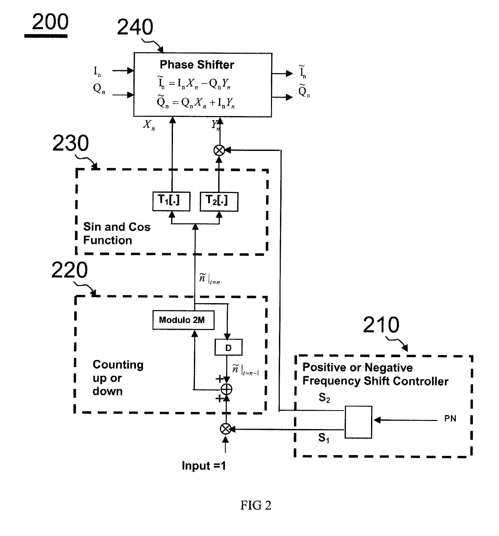
A TYPE B Implementation

[0082]fs=7⁢⁢MHz,ϕ=2⁢π⁡(fΔfs)=2⁢π⁡(±7⁢N±1.57⁢π)=(±14⁢N±37⁢π),

where frequency shift fΔ=(±7N±1.5) MHz and

N is an arbitrary positive integer. Obviously, K=3 and M=7 in this example.

The reference time index is found as follows:

[0083] n~t=n={ n~t=n-1+S1-14,if⁢⁢ n~t=n-1+S1≥14 n~t=n-1+S1+14,if⁢⁢ n~t=n-1+S1<0 n~t=n-1+S1,otherwise.

where S1=1 or S1=−1 if counting up or counting down is required, respectively.

In short, a modulo 2Kπ (or 6π) operation is equivalent to a modulo 2M (or 14) operation.

The required two LUT are found as follows:

[0084]T1⁡[m]=cos⁡(m⁢K⁢⁢πM)=cos(m⁢3⁢π7),m=0,1,2,…⁢,13.⁢⁢T2⁡[m]=sin⁡(m⁢K⁢⁢πM)=sin(m⁢3⁢π7),m=0,1,2,…⁢,13.(EQ⁢-⁢23)

[0085]And the required cos and sin function values to calculate (EQ-3) or (EQ-4) are shown as follows.

cos θn=T1[ñ] and sin θn=T2[ñ], ∀n.

[0086]The size of the required LUT is 4M=28 entries. In this example, the two LUTs are specially designed for a particular K=3 only. If another desired frequency shift (i.e., a different K) is...

example 3

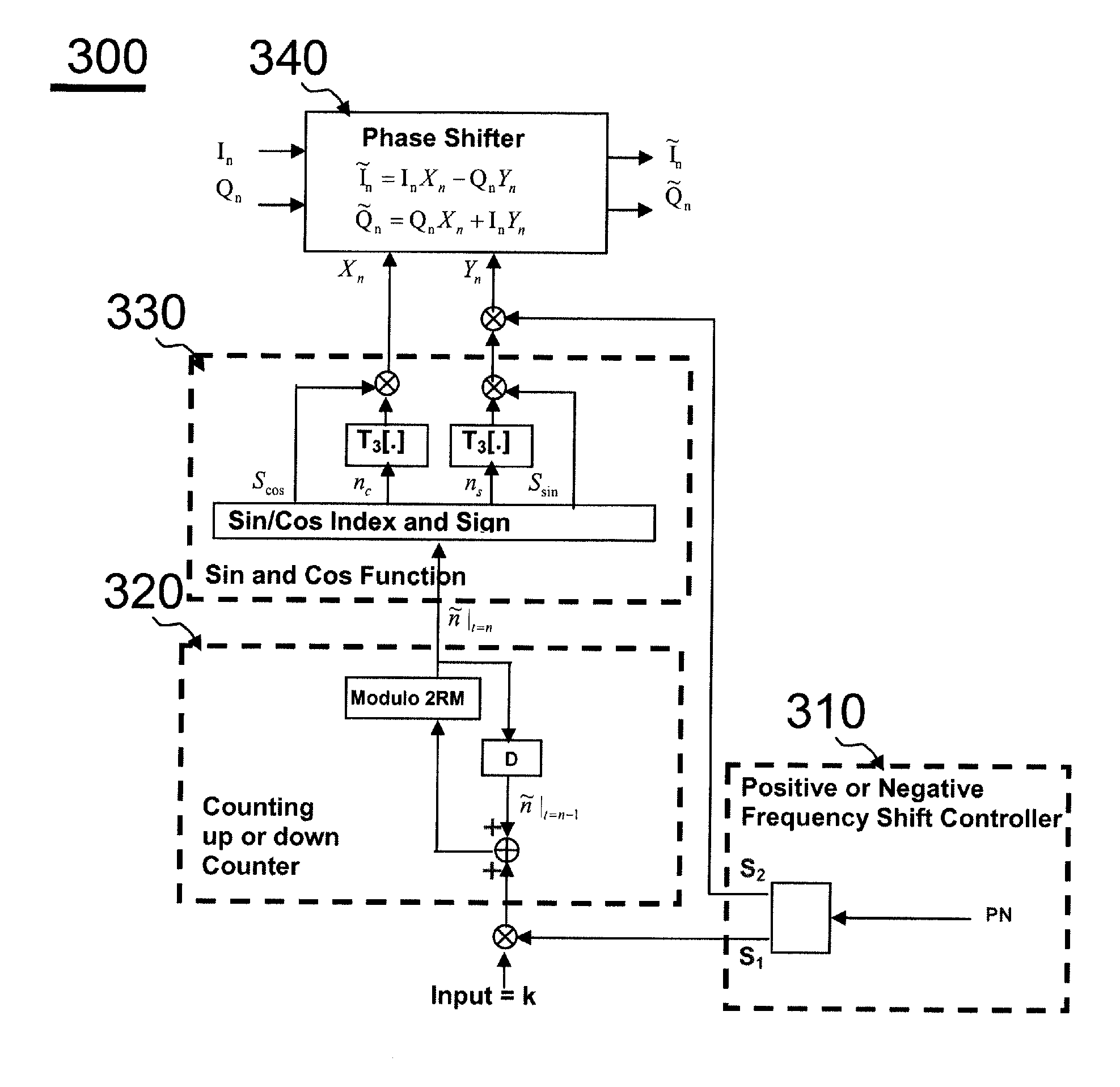
An Implementation of TYPE C1 Frequency Shifter 300 of the Present Invention with R=1

[0088]fs=7⁢⁢MHz,⁢ϕ=2⁢π⁡(fΔfs)=2⁢π⁡(±7⁢N±K×0.57⁢π)=(±14⁢N±K7⁢π),(EQ⁢-⁢24)

where arbitrary fΔ=(±7N±K×0.5)={circumflex over (K)}×0.5=0, ±0.5, ±1, ±1.5, ±2, ±2.5, . . . , MHz,

N is an arbitrary positive integer, K is an arbitrary integer between 0 and 13, and {circumflex over (K)} is an arbitrary integer (from the smallest integer to the largest one in theory). Obviously, R=1 and M=7 in this example. In short, by controlling integer K from 0 to 13, an arbitrary frequency shift which is an integer multiple of 0.5 MHz can be achieved. The reference time index is found as follows:

[0089] n~t=n={ n~t=n-1+S1×K-14,if⁢⁢ n~t=n-1+S1×K≥14 n~t=n-1+S1×K+14,if⁢⁢ n~t=n-1+S1×K<0 n~t=n-1+S1×K,otherwise.(EQ⁢-⁢25)

where S1=1 or S1=−1 if counting up or counting down is required, respectively.

In short, a modulo 2π operation is equivalent to a modulo 2RM (or 14) operation. The required one LUT is found as follows:

[0090]T3⁡[m]...

example 4

An Implementation of TYPE C2 Frequency Shifter 300 of the Present Invention with R=2

[0092]fs=14⁢⁢MHz,⁢ϕ=2⁢π⁡(fΔfs)=2⁢π⁡(±14⁢N±K×0.514⁢π)=(±28⁢N±K2×7⁢π),(EQ⁢-⁢28)

where arbitrary fΔ=(±28N±K×0.5)={circumflex over (K)}×0.5=0, ±0.5, ±1, ±1.5, ±2, ±2.5, . . . , MHz

N is an arbitrary positive integer, K is an arbitrary integer between 0 and 27, and {circumflex over (K)} is an arbitrary integer. Obviously, R=2 and M=7 in this example. In short, by controlling integer K from 0 to 27, an arbitrary frequency shift which is an integer multiple of 0.5 MHz. The reference time index is found as follows:

[0093] n~t=n={ n~t=n-1+S1×K-28,if⁢⁢ n~t=n-1+S1×K≥28 n~t=n-1+S1×K+28,if⁢⁢ n~t=n-1+S1×K<0 n~t=n-1+S1×K,otherwise.(EQ⁢-⁢29)

where S1=1 or S1=−1 if counting up or counting down is required, respectively.

In short, a modulo 2π operation is equivalent to a modulo 2RM (or 28) operation. The required one LUT is the same as (EQ-26):

[0094]T3⁡[m]=sin⁡(m⁢π2×7)=sin⁡(m⁢π14),⁢m=0,1,2,…⁢⁢7.(EQ⁢-⁢30)

And the required...


PUM


Abstract

This invention describes a programmable, digital implementation to shift an arbitrary frequency, or various frequencies in various communication systems of the original signal in the frequency domain. The correspondent phase accumulation to perform the desired frequency shift per sampling instant is perfectly tracked by counting up or down a simple integer. Several arbitrary frequency shifters with different mathematical models are provided. The correspondent implementations with Look-Up-Tables (LUT) are derived for high-speed implementations without further calculations of the values of the sine and cosine functions every sampling instant. Furthermore, a simple shift-and-add phase rotation is described to replace the four required real multiplications. If the original complex signal contains only one-bit each from real part and imaginary part, a surprisingly simple implementation is derived and disclosed for the overall arbitrary frequency shift operation. Further simplifications are also disclosed to make this invention feasible for high sampling frequencies and small frequency drifts.

Description

BACKGROUND OF THE INVENTION[0001]1. Field of the Invention[0002]The present invention relates generally to a frequency shifter used for wireless communication systems and more particularly relates to an arbitrary frequency shifter extremely useful for a digital communication system designed to operate with various communication systems which are centered at different frequencies in the frequency domain.[0003]2. Background Art[0004]Various wireless standards and communication systems are available in the market, e.g., cellular phones, wireless local area network (WLAN) systems, and Bluetooth devices. In practice, the signal is up-converted to a much higher radio frequency (RF) and is transmitted. It is the designer's choice to down-convert the RF signal directly to baseband or through an intermediate frequency (IF) first and then apply a digital phase shifter to down-convert the signal to baseband. With the growth of markets, it is of great interests to integrate different systems in...

Claims


Application Information

Patent Timeline
Patent Type & Authority Patents(United States)
IPC IPC(8): H03K9/00H04L27/00
CPCG06F1/022G06F1/0342
Inventor CHEN, JENG-HONG
Owner MICROCHIP TECH INC
Why Eureka
Try Eureka