Method and apparatus for providing dynamically variable time delay for ultrasound beamformer

A technology of beam formers and beams, which is applied in the directions of sound wave reradiation, ultrasonic/sonic wave/infrasonic wave diagnosis, and sound-generating devices, and can solve problems such as discontinuity and interpolator performance degradation

Inactive Publication Date: 2005-01-12
GENERAL ELECTRIC CO
View PDF0 Cites 0 Cited by
  • Summary
  • Abstract
  • Description
  • Claims
  • Application Information

AI Technical Summary

Problems solved by technology

Dynamic changes in FIFO delays create discontinuities at t...

Method used


Image

  • Method and apparatus for providing dynamically variable time delay for ultrasound beamformer
  • Method and apparatus for providing dynamically variable time delay for ultrasound beamformer
  • Method and apparatus for providing dynamically variable time delay for ultrasound beamformer

Examples


Embodiment Construction

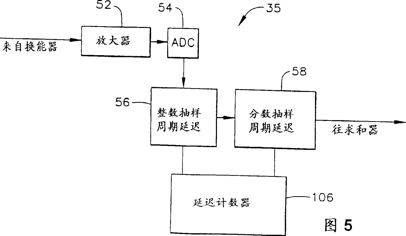
[0067] Referring to Fig. 5, according to the present invention, each received signal processing channel 35 includes an amplifier 52, which amplifies the signal detected by the respective ultrasonic transducer unit; an analog-to-digital converter 54, which amplifies the analog the signal is converted to a stream of digital samples at some sample rate (e.g., each digital sample has 8 bits); an integer sample period delay circuit 56 for delaying the digital samples by a time interval equal to an integer number of sample periods; and fractional Sample period delay circuit 58 for delaying the digital samples by a time interval equal to a fraction of the sample period. The outputs of the respective fractional sample period delay circuits for each processing channel are then summed in summer 36, as image 3 shown.

[0068] In accordance with the present invention, the integer sample period delay circuit includes a dynamic FIFO 101 and a series of pulse-timed pipeline registers 102-10...


PUM


Abstract

A phased array sector scanning ultrasonic system includes a separate receive channel for each respective element in an ultrasonic transducer array. Each receive channel imparts a delay to the echo signal produced by each respective element. The delayed echo signals are summed to form a steered, dynamically focused and dynamically windowed receive beam even when the transmit beam does not emanate from the center of the array. The receiver has a beamformer including a multiplicity of beamformer channels. The beamformer dynamically increases delays to each channel without introducing unwanted discontinuities, by combining and synchronizing a FIFO and an interpolator. The interpolator uses "Wallace tree" adders to accumulate bit-shifted versions of the inputs. The number of additions is less than the number of bits which would be needed to represent equivalent coefficients. This reduces the hardware relative to a conventional implementation which incorporates multipliers with shifts and adds equaling the number of bits in the coefficients.

Description

technical field [0001] The present invention relates generally to ultrasound imaging systems for forming ultrasound beams by delaying and summing return signals in a number of parallel channels. In particular, the present invention relates to means for providing the required beamforming latency for channel processing. Background technique [0002] Conventional ultrasound imaging systems include an array of ultrasound transducers that emit beams of ultrasound and then receive the beams reflected from the object of interest. For ultrasound imaging, the array typically has many transducers aligned in a line driven by independent voltages. By selecting the time delay (or phase) and magnitude of the applied voltages, the individual transducers can be controlled to produce ultrasonic waves that combine into a net ultrasonic wave that travels in a preferred vector direction and is focused along the beam at a selected point. Multiple transmissions may be used to obtain data repre...

Claims


Application Information

Patent Timeline
IPC IPC(8): G01N29/44A61B8/00G01S7/52G01S7/523G01S15/89G10K11/34H04R17/00
CPCG01S7/52034G01S15/8915G10K11/345G01S15/8918G01S7/52025G01S7/52046G01S7/526
Inventor S·C·米勒G·A·利勒加尔德D·C·米龙
Owner GENERAL ELECTRIC CO
Why Eureka
Try Eureka