
Automatic detecting system and method for intelligent grid data collecting terminal

A technology of data acquisition terminal and smart grid, applied in measurement devices, measurement of electrical variables, instruments, etc., can solve the problems of inconvenient assembly line operations, the number of instruments and workers, and the difficulty of worker training, etc., to improve detection efficiency and detection. Correctness, avoid the effect of waiting between stations

Active Publication Date: 2012-07-04
BEIJIG YUPONT ELECTRIC POWER TECH +1
View PDF3 Cites 31 Cited by
  • Summary
  • Abstract
  • Description
  • Claims
  • Application Information

AI Technical Summary

Problems solved by technology

This scheme has two organizational forms. One is to detect multiple parameters at the same station. The disadvantage is that the functions and gears of the detection instruments need to be adjusted frequently, which makes it difficult to train workers and is not convenient for assembly line operations; One form of organization is to arrange a number of testing stations, and each station adjusts the instruments and meters to fixed functions and gears, and detects fixed parameters. The disadvantage of this method is that the number of instruments and workers required is large, and it takes up The area of ​​the venue is large
The inspection process control and inspection result interpretation of these two organizational forms rely on manual execution, and misjudgment of results due to manual fatigue is inevitable

Method used


Image

  • Automatic detecting system and method for intelligent grid data collecting terminal
  • Automatic detecting system and method for intelligent grid data collecting terminal
  • Automatic detecting system and method for intelligent grid data collecting terminal

Examples


Embodiment Construction

[0035] In order to make the purpose, technical solutions and advantages of the embodiments of the present invention more clear, the embodiments of the present invention will be further described in detail below in conjunction with the accompanying drawings. Here, the exemplary embodiments and descriptions of the present invention are used to explain the present invention, but not to limit the present invention.

[0036] The embodiment of the present invention adopts an organizational structure of a server plus a client, and provides an automatic detection system for smart grid data collection terminals, so as to meet the needs of batch production line detection of smart grid data collection terminals.

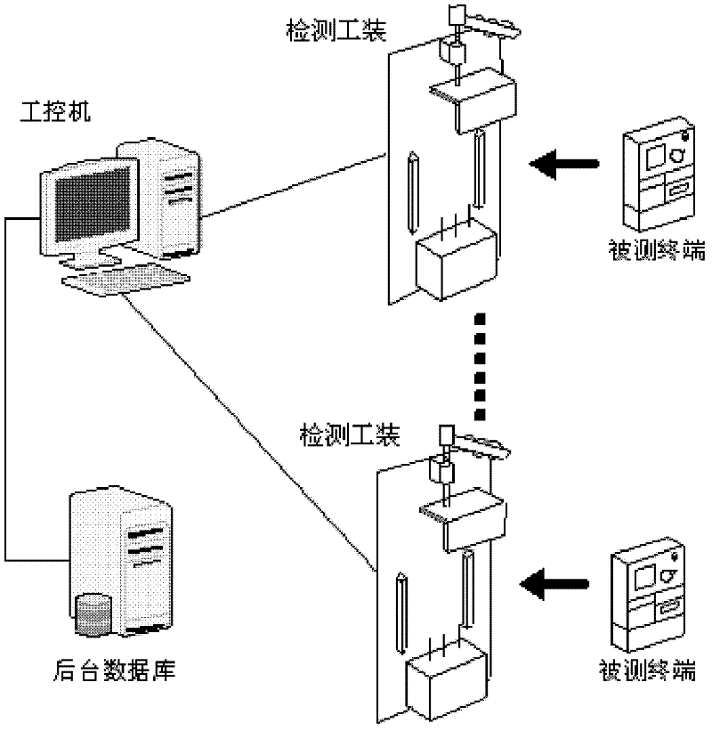
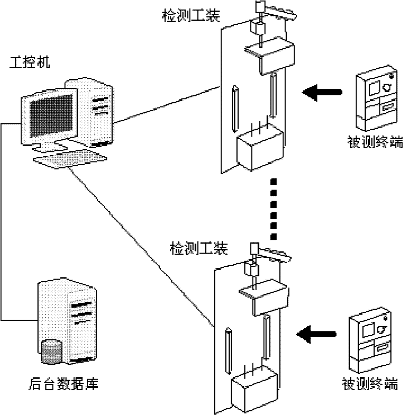
[0037] Such as figure 1 As shown, the automatic detection system of the smart grid data acquisition terminal in the embodiment of the present invention may include:

[0038] Back-end database, industrial computer, testing tool, wherein the background database is connected to t...


PUM


Abstract

The invention discloses an automatic detecting system and a method for an intelligent grid data collecting terminal. The system comprises a backend database, an industrial personal computer (IPC) and a detecting tooling. The backend database memorizes detecting configuration parameters and detecting conclusion information. The IPC receives the request for detecting a detected terminal and sent by the detecting tooling, reads the detecting configuration parameters from the backend database, and sends detecting item reports to the detecting tooling. The IPC receives detecting results sent back by the detecting tooling and obtains the detecting conclusion information according to the detecting results, memorizes the detecting conclusion information into the backend database and sends the detecting conclusion information to the detecting tooling. The detecting tooling sends the detecting request to the IPC and receives the detecting item reports; if the detecting item reports need to be processed by the detecting tooling, the detecting tooling processes the detecting item reports and sends back the detecting results; if the detecting item reports need to be processed and detected by the detected terminal, the detecting item reports are forwarded to the detected terminal, and the detected terminal sends back the detecting results to the IPC through the detecting tooling; and the IPC receives and displays the detecting conclusion information. The automatic detecting system and the method for the intelligent grid data collecting terminal can improve detecting efficiency and correctness.

Description

technical field [0001] The invention relates to the technical field of smart grids, in particular to an automatic detection system and method for smart grid data collection terminals. Background technique [0002] In May 2009, the State Grid Corporation of China officially released the "Strong Smart Grid" development strategy, and my country entered a new era of smart grid construction. The automatic collection of electric energy information data is the premise of realizing the intelligent management of the power grid, and it will be the first to benefit from the construction of the smart grid. The smart grid data acquisition terminal is the core equipment of the automatic energy information acquisition system, which has ushered in a new development opportunity, and its market demand is growing rapidly. According to statistics, in 2011 there were about 50 million smart meters used to replace traditional electric energy meters, and the corresponding new demand for data colle...

Claims


Application Information

Patent Timeline
IPC IPC(8): G01R35/04
Inventor 段磊桑学宁汪义平
Owner BEIJIG YUPONT ELECTRIC POWER TECH
Learn More