
Polarization reconfigurable high-gain panel antenna

A flat-panel antenna, high-gain technology, applied in the antenna, radiation element structure, electrical components, etc., can solve the problems of complex feed network and control circuit, low polarization purity, and increase the difficulty of layout, so as to improve the polarization Purity, high polarization purity, ease of transport and postulated effects

Inactive Publication Date: 2012-07-04
UNIV OF ELECTRONICS SCI & TECH OF CHINA
View PDF2 Cites 19 Cited by
  • Summary
  • Abstract
  • Description
  • Claims
  • Application Information

AI Technical Summary

Problems solved by technology

[0003] Most of the existing polarization reconfigurable antennas adopt microstrip structure, but a single microstrip polarization reconfigurable antenna has a gain of only 6-9dB due to the limitation of its radiation aperture.
If the gain is increased by using the traditional array method, the feed network and control circuit will be very complicated
On the one hand, the complex feed network will cause large antenna loss and reduce antenna efficiency, on the other hand, it will increase the difficulty of layout
However, complex control circuits will cause low polarization purity due to the inevitable delay between array elements.

Method used


Image

  • Polarization reconfigurable high-gain panel antenna
  • Polarization reconfigurable high-gain panel antenna
  • Polarization reconfigurable high-gain panel antenna

Examples


Embodiment Construction

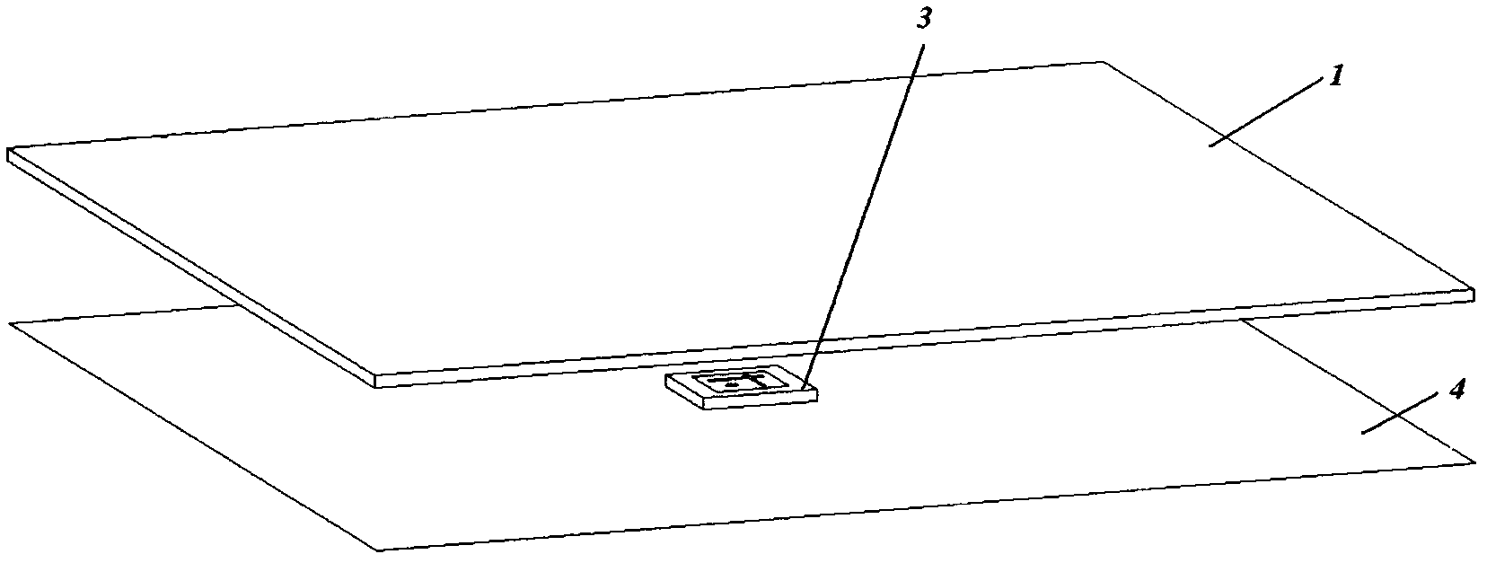
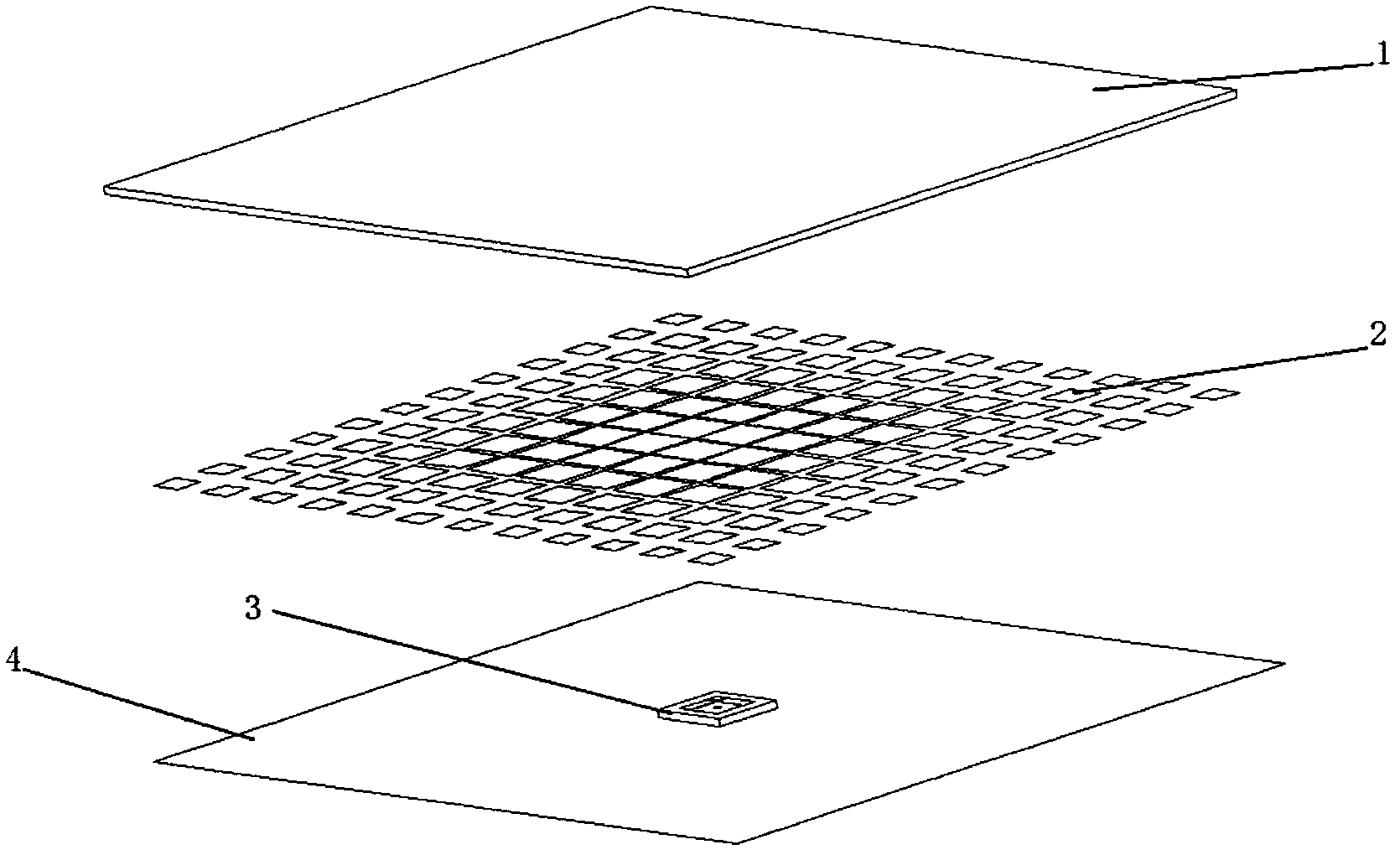
[0025] A polarization reconfigurable high-gain panel antenna includes a dielectric cover 1 , a frequency selective surface 2 , a polarization reconfigurable feed antenna 3 and a floor 4 . The dielectric cover 1 is on the top, the frequency selective surface 2 is located on the lower surface of the dielectric cover, and the polarization reconfigurable feed antenna 3 is located on the floor 4; the frequency selective surface 2 is arranged in the same period but the size is gradually changed; the feed antenna 3. It includes a dielectric board 3-1 and a radiation patch 3-2. There are two mutually orthogonal slots 3-3 on the radiation patch. There is a control switch 3-4 in the middle of each slot. The radiation patch is composed of Coaxial inner conductor 3-5 excitation.

[0026] The dielectric substrate and the feed antenna dielectric substrate have a dielectric constant of 2.65 and a thickness of 1 mm. The distance H between the dielectric substrate and the floor was 13.8 mm. ...


PUM


Abstract

The invention provides a polarization reconfigurable high-gain panel antenna. 21dBi gain can be achieved and aperture efficiency can achieve 70% by only one feed antenna; and furthermore, by switching control, the polarization state of the antenna can be converted between left-hand circular polarization and right-hand circular polarization, a complex feed network and a control circuit are eliminated, and the polarization reconfigurable high-gain panel antenna has the advantages of simple feed, low loss, high efficiency, easiness in control and high polarization purity.

Description

technical field [0001] The invention relates to a polarization reconfigurable high-gain panel antenna, in particular to a polarization-reconfigurable high-gain panel antenna with simple structure, low cost, and easy realization and control. Background technique [0002] With the increasing requirements of modern radar and communication systems, antenna systems are becoming more and more complex, and it is of great significance to reduce the number, size and weight of antennas. In order to achieve this goal, people have proposed the concept of reconfigurable antennas in recent years. At present, PIN diode switches, optical control devices, RF microwave MEMS switches and other methods are mainly used to control and change the aperture and structure of the antenna to achieve frequency, pattern and polarity. The reconstruction of the way of transformation and so on. The polarization reconfigurable antenna is a kind of reconfigurable antenna, which can reconfigure the polarizati...

Claims


Application Information

Patent Timeline
IPC IPC(8): H01Q1/38H01Q15/24H01Q19/00H01Q19/10
Inventor 欧阳骏韩旺旺杨峰王良翼张凯之
Owner UNIV OF ELECTRONICS SCI & TECH OF CHINA
Learn More