Low-speed permanent-magnet motor rotor

A technology for permanent magnet motors and rotors, applied in the direction of magnetic circuit rotating parts, magnetic circuit shape/style/structure, etc., can solve the problems of complete machine scrapping, motor jamming, and affecting the performance of motor rotors, etc.

Inactive Publication Date: 2012-07-04
DALIAN YULIN ELECTRIC MOTOR
View PDF0 Cites 0 Cited by
  • Summary
  • Abstract
  • Description
  • Claims
  • Application Information

AI Technical Summary

Problems solved by technology

[0002] In the prior art, the permanent magnets of the rotor of the low-speed permanent magnet motor are generally installed directly outside the rotor or blocked on the periphery of the rotor through a baffle. In this way, when the air gap of the motor is small, the loose permanent magnets are likely to exceed The air gap will cause the motor to be stuck, and the whole machine will be scrapped, and the original rotor is generally in the form of a single magnetic pole, which will affect the working performance of the motor rotor

Method used


Image

  • Low-speed permanent-magnet motor rotor
  • Low-speed permanent-magnet motor rotor
  • Low-speed permanent-magnet motor rotor

Examples


Embodiment Construction

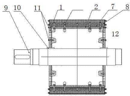
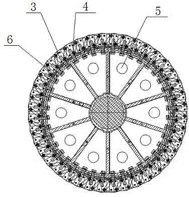
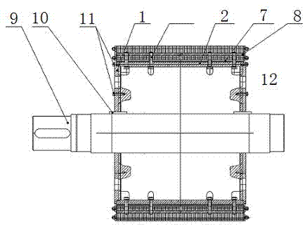
[0013] Such as figure 1 with figure 2 As shown, the low-speed permanent magnet motor rotor includes an end plate 1, a rotor inner sleeve 2, a magnetic pole 3, a permanent magnet block 4, and a ventilation hole 5. The magnetic pole 3 is connected to the rotor inner sleeve 2 by a tightening bolt 12, and the two magnetic poles 3 are opposite to each other. The frame is inlaid with permanent magnet blocks 4, the ventilation holes 5 are arranged on the rotor end plate 1, each magnetic pole 3 is connected by a magnetic pole pad 6, and the lower end of the magnetic pole 3 is provided with a magnetic isolation pad 7, and each magnetic pole 3 contains multiple permanent magnet blocks In series combination, the magnetic pole 3 is provided with a square key 8, the rotor is fixed on the motor shaft 9, an anti-twist key 10 is provided between the rotor and the motor shaft 9, and a fixing bolt 11 is provided on the rotor end plate 1. The low-speed permanent magnet of the present invention T...


PUM


Abstract

The invention discloses a low-speed permanent-magnet motor rotor, which comprises end plates (1), a rotor inner sleeve (2), magnetic poles (3), permanent magnets (4) and ventilation holes (5), wherein the magnetic poles (3) are connected with the rotor inner sleeve (2) through fastening bolts (12), the permanent magnets (4) are embedded on opposite frames of the two magnetic poles (3), and the ventilation holes (5) are formed on the rotor end plates (1). According to the low-speed permanent-magnet motor rotor disclosed by the invention, the assembly quantity of the magnetic poles is determined by adopting a circumference magnetic pole combination mode according to magnetic poles of a motor, and fixed keys are designed arranged on shaft extension and the two end plates and used for preventing the rotor from integrally rotating under large torque action; the magnetic poles are fastened by the fastening bolts and the rotor inner sleeve, and the bolts are provided with fastening glue which is used for preventing the bolt from loosening; the permanent magnets are embedded in the opposite frames of the two magnetic poles, a plurality of permanent magnets are combined in series in each magnetic pole, and each magnetic pole is connected by a magnetic pole pad, so that magnetic flux closing is ensured; and the rotor end plates are provided with the ventilation holes, so that internal air volume is ensured, and thus the rotor can normally work under the set temperature.

Description

Technical field [0001] The invention relates to a low-speed permanent magnet motor rotor. Background technique [0002] In the prior art, the permanent magnet block of the rotor of the low-speed permanent magnet motor is generally directly installed outside the rotor or blocked by the baffle on the periphery of the rotor. In this way, when the air gap of the motor is small, the loose permanent magnet block is extremely likely to exceed The air gap causes the motor to jam and the whole machine is scrapped, and the original rotor is generally in the form of a single magnetic pole, which affects the working performance of the motor rotor. Summary of the invention [0003] The object of the present invention is to provide a low-speed permanent magnet motor rotor. [0004] The technical solution adopted by the present invention to achieve the above objective is: a low-speed permanent magnet motor rotor, including an end plate (1), a rotor inner sleeve (2), a magnetic pole (3), a permane...

Claims


Application Information

Patent Timeline
IPC IPC(8): H02K1/27H02K1/32
Inventor 孙淑娥
Owner DALIAN YULIN ELECTRIC MOTOR
Why Eureka
Try Eureka