
Switched reluctance motor with radial and transverse magnetic field characteristics
A switched reluctance motor and transverse magnetic field technology, which is applied to electrical components, electromechanical devices, and static components of magnetic circuits, can solve the problems of single air gap magnetic field and limit the power density of motors, and achieve high power density and low speed Drag occasions, the effect of high utilization
- Summary
- Abstract
- Description
- Claims
- Application Information
AI Technical Summary
Problems solved by technology
Method used
Image

Examples
Embodiment Construction
[0026] The present invention is described in more detail below in conjunction with accompanying drawing example:
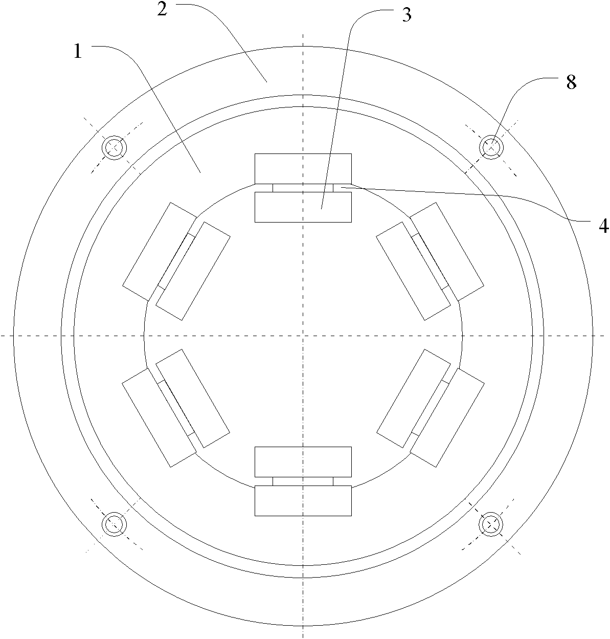
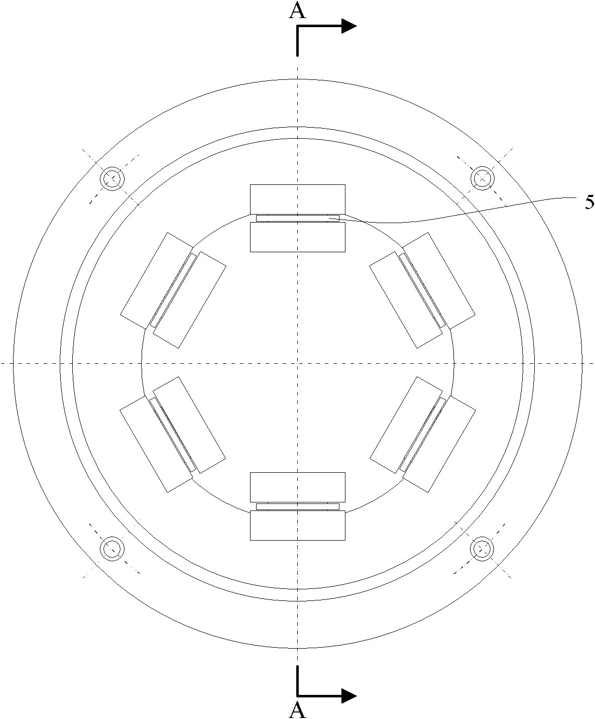
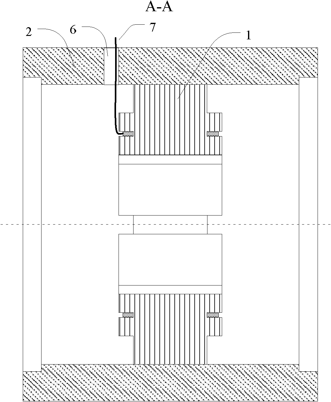
[0027] combine Figure 1-12 , a switched reluctance motor with multi-directional magnetic field characteristics proposed by the present invention, structurally includes a stator, an intermediate rotor, a left rotor, a right rotor, and a shaft. The specific structure is as follows:
[0028] (1) Stator structure. The stator core 1 has a cylindrical structure; the stator core 1 is installed inside the casing 2; a plurality of stator poles 3 are evenly distributed along the circumferential direction of the stator core 1, and each stator pole 3 protrudes beyond the stator core 1 radial direction. The inner surface protrudes from the two end faces of the stator core 1 along the axial direction; the four sides of the stator pole 3 are provided with annular grooves 4; the stator windings 5 are placed in the annular grooves 4, and the stator windings 5 are composed o...
PUM
 Abstract
Description
Claims
Application Information