Cutting insert and cutting tool, and cut workpiece manufacturing method using same
A technology for cutting inserts and cutting tools, which is applied in the direction of milling cutting blades, manufacturing tools, metal processing equipment, etc., can solve the problems of increased cutting resistance, and achieve the goals of reducing cutting resistance, good finishing surface, and improving chip discharge Effect
- Summary
- Abstract
- Description
- Claims
- Application Information
AI Technical Summary
Problems solved by technology
Method used
Image
Examples
no. 1 approach
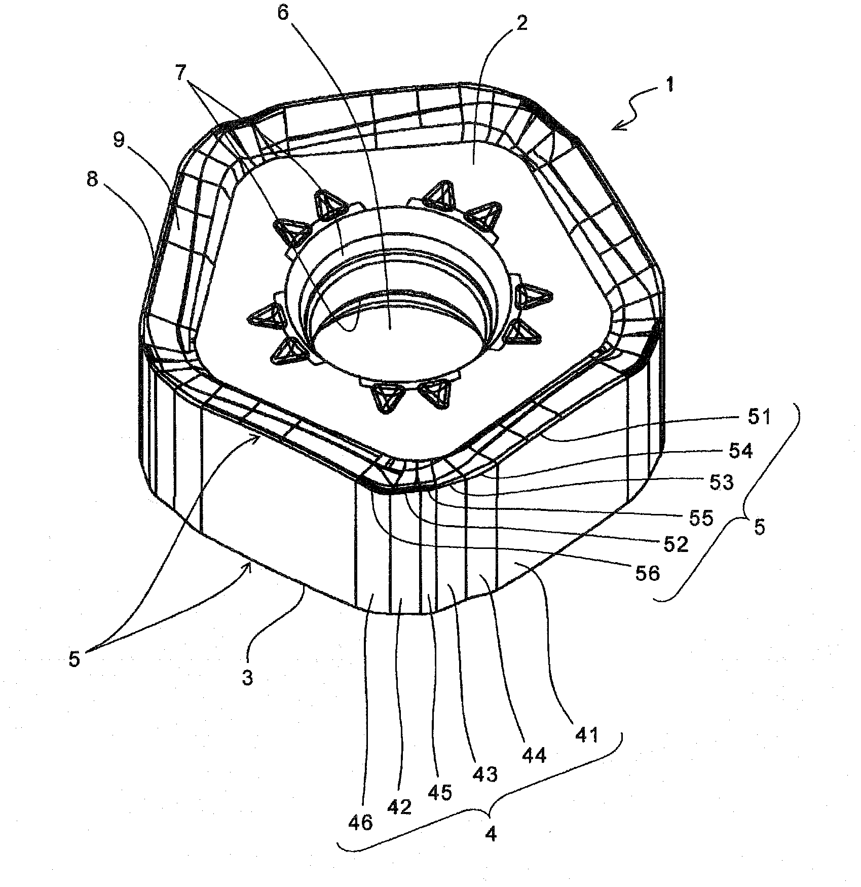
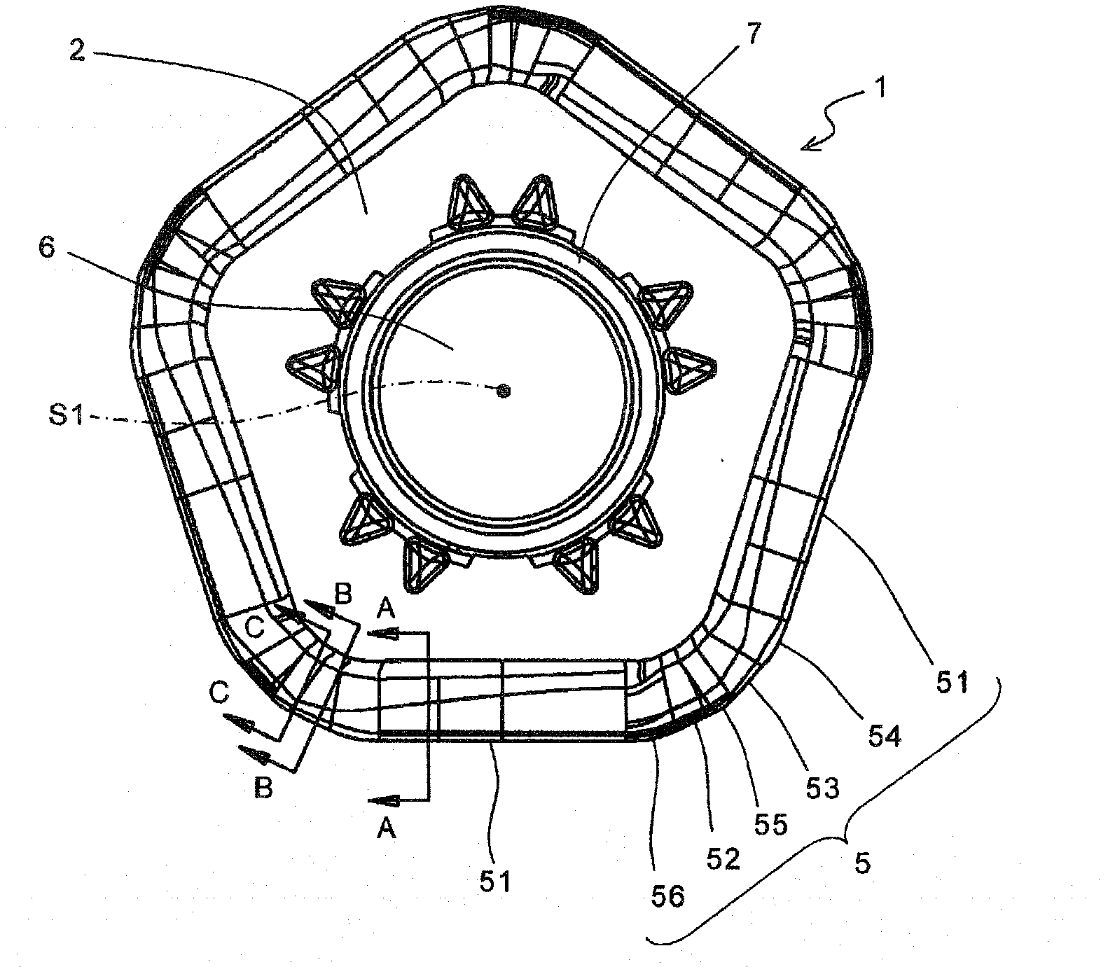
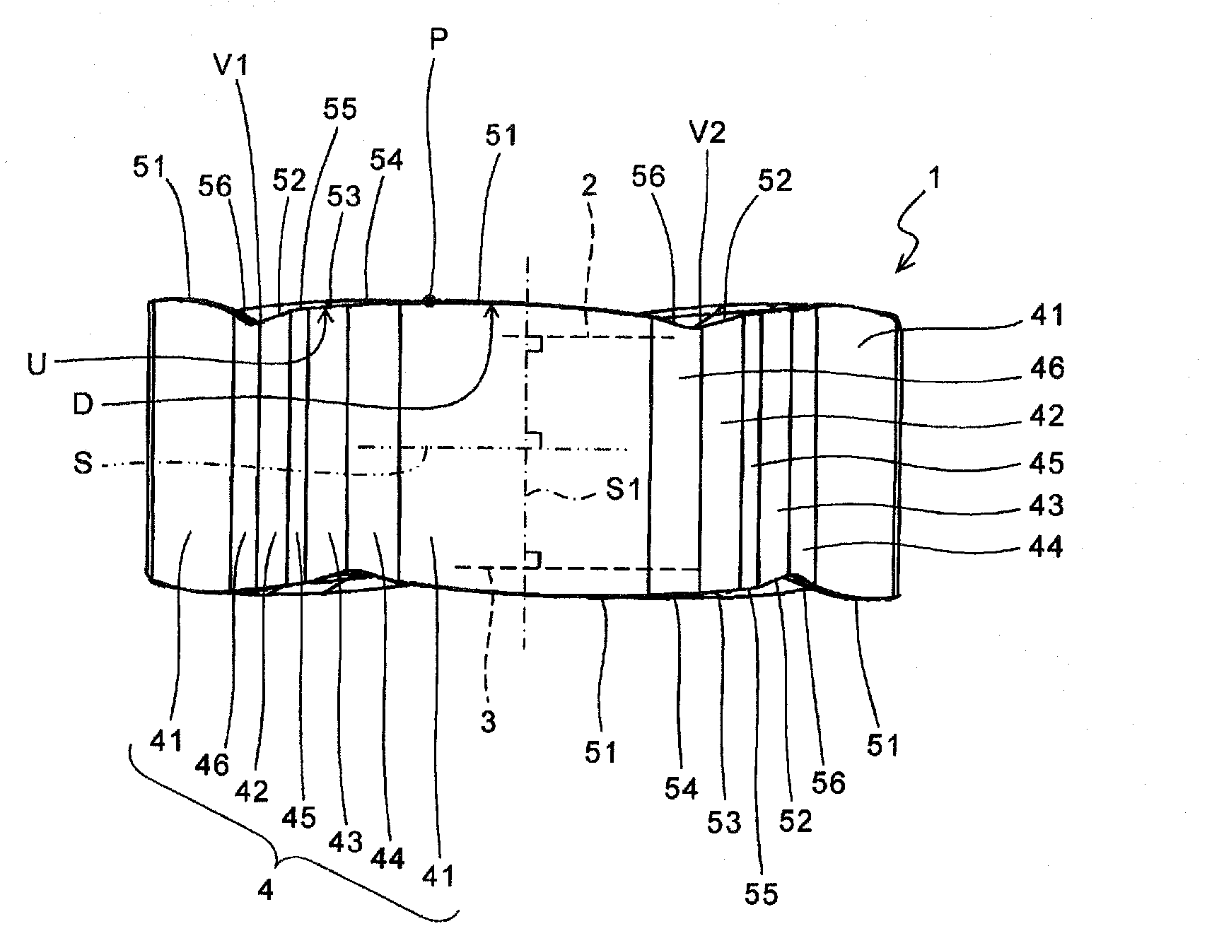
[0029] Below, refer to Figure 1 to Figure 4 A first embodiment of the cutting insert (hereinafter, sometimes referred to as "insert") according to the present invention will be described in detail.
[0030] like figure 1 As shown, the insert 1 has a substantially polygonal plate-shaped body portion. The shape of the main body portion is not particularly limited as long as it is a shape commonly used in inserts by those skilled in the art, such as a triangle, a quadrangle, a pentagon, a hexagon, and an octagon in plan view. In the present embodiment, since the main body portion has a substantially pentagonal shape, as will be described later, it is easy to form minor cutting edges in addition to the major cutting edges, and there is an advantage that it is easy to secure a large mounting seat surface.
[0031] The body portion is preferably composed of, for example, a cemented carbide base body, a cermet base body, or the like. It is preferable to form a PVD film or a CVD f...
no. 2 approach
[0052] Second, refer to Figure 5 to Figure 8 A second embodiment of the insert according to the present invention will be described in detail. It should be noted that in Figure 5 to Figure 8 , to the same as the above Figure 1 to Figure 4 The same structural parts are assigned the same symbols and the description is omitted.
[0053] like Figure 5 As shown, the insert 11 of the present embodiment has a substantially polygonal plate-shaped body portion. In the present embodiment, as in the first embodiment, the main body portion has a substantially pentagonal shape having five long sides.
[0054] The main body has: a part of the upper surface 12 that functions as a so-called rake (face); a part of the lower surface 13 that functions as a mounting surface (mounting seat surface) with respect to the tool holder; and is continuous with the upper surface 12 and the lower surface 13 And a part has the side surface 14 which functions as a so-called flank. A cutting edge 15...
no. 3 approach
[0090] Second, refer to Figure 12 and Figure 13 A third embodiment of the cutting tool according to the present invention will be described in detail. It should be noted that in Figure 12 and Figure 13 , in the same Figure 9 to Figure 11 The same components are assigned the same symbols, and descriptions are omitted. like Figure 12 and Figure 13 As shown, the cutting tool 90 according to the present embodiment is a cutting tool in which a plurality of inserts 11 are attached to a holder 91 .
[0091] Specifically, similar to the tool holder 81 according to the first embodiment, a plurality of insert grooves 92 are formed in the outer peripheral front end portion of the tool holder 91 at intervals in the circumferential direction. In addition, the insert 11 is attached to the attachment surface 93 of each insert pocket 92 .
[0092] The insert 11 is attached to the tool holder 91 so that the upper surface 12 thereof faces the front side in the rotational directio...
PUM
 Abstract
Description
Claims
Application Information
 - R&D
- Intellectual Property
- Life Sciences
- Materials
- Tech Scout
- Unparalleled Data Quality
- Higher Quality Content
- 60% Fewer Hallucinations
Browse by: Latest US Patents, China's latest patents, Technical Efficacy Thesaurus, Application Domain, Technology Topic, Popular Technical Reports.
© 2025 PatSnap. All rights reserved.Legal|Privacy policy|Modern Slavery Act Transparency Statement|Sitemap|About US| Contact US: help@patsnap.com


