Support of propeller unit for a vessel

A technology for propellers and ships, applied in the field of propeller unit supports, can solve problems such as discomfort for crew members and passengers, shortening of effective life, etc.

Active Publication Date: 2012-07-04
康斯博海运公司
View PDF6 Cites 10 Cited by
  • Summary
  • Abstract
  • Description
  • Claims
  • Application Information

AI Technical Summary

Problems solved by technology

This will result in a shortened useful life of components and / or elements necessitating more frequent inspections and / or maintenance of the thruster unit
In addition, the vibrations experienced by the thruster unit can also be transmitted to the vessel on which the thruster unit is installed, causing discomfort to the crew and passengers on board the vessel

Method used


Image

  • Support of propeller unit for a vessel
  • Support of propeller unit for a vessel
  • Support of propeller unit for a vessel

Examples


Embodiment Construction

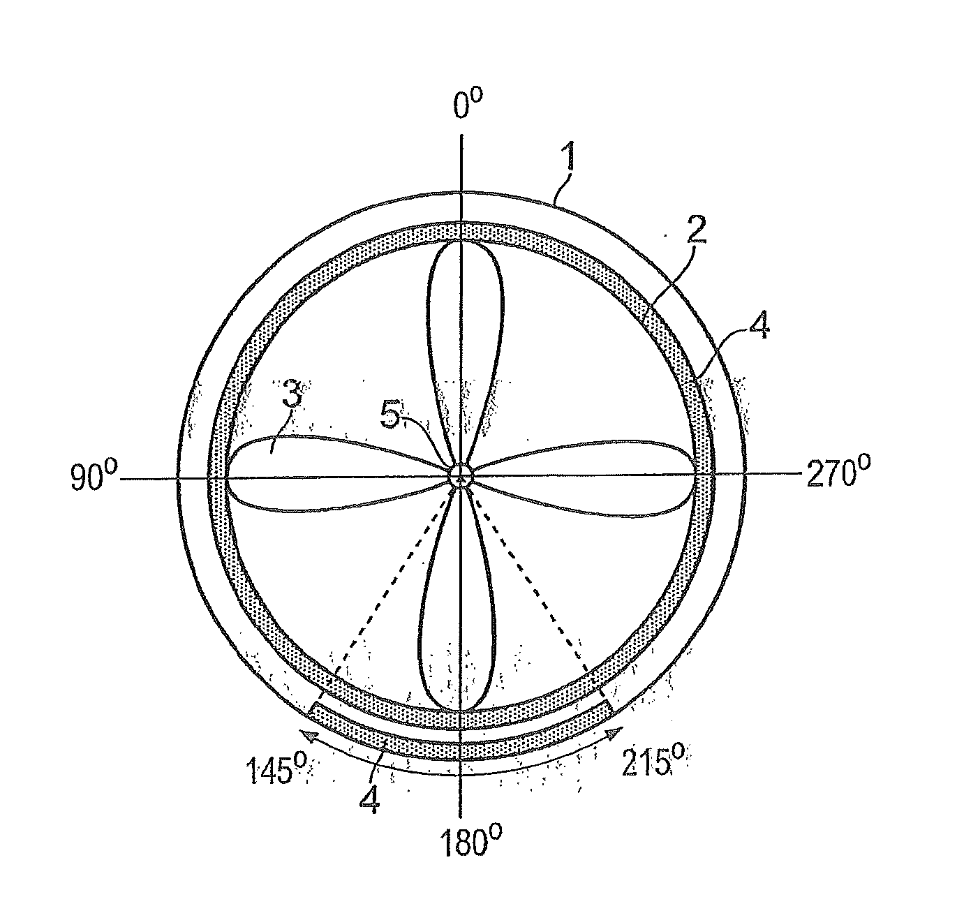
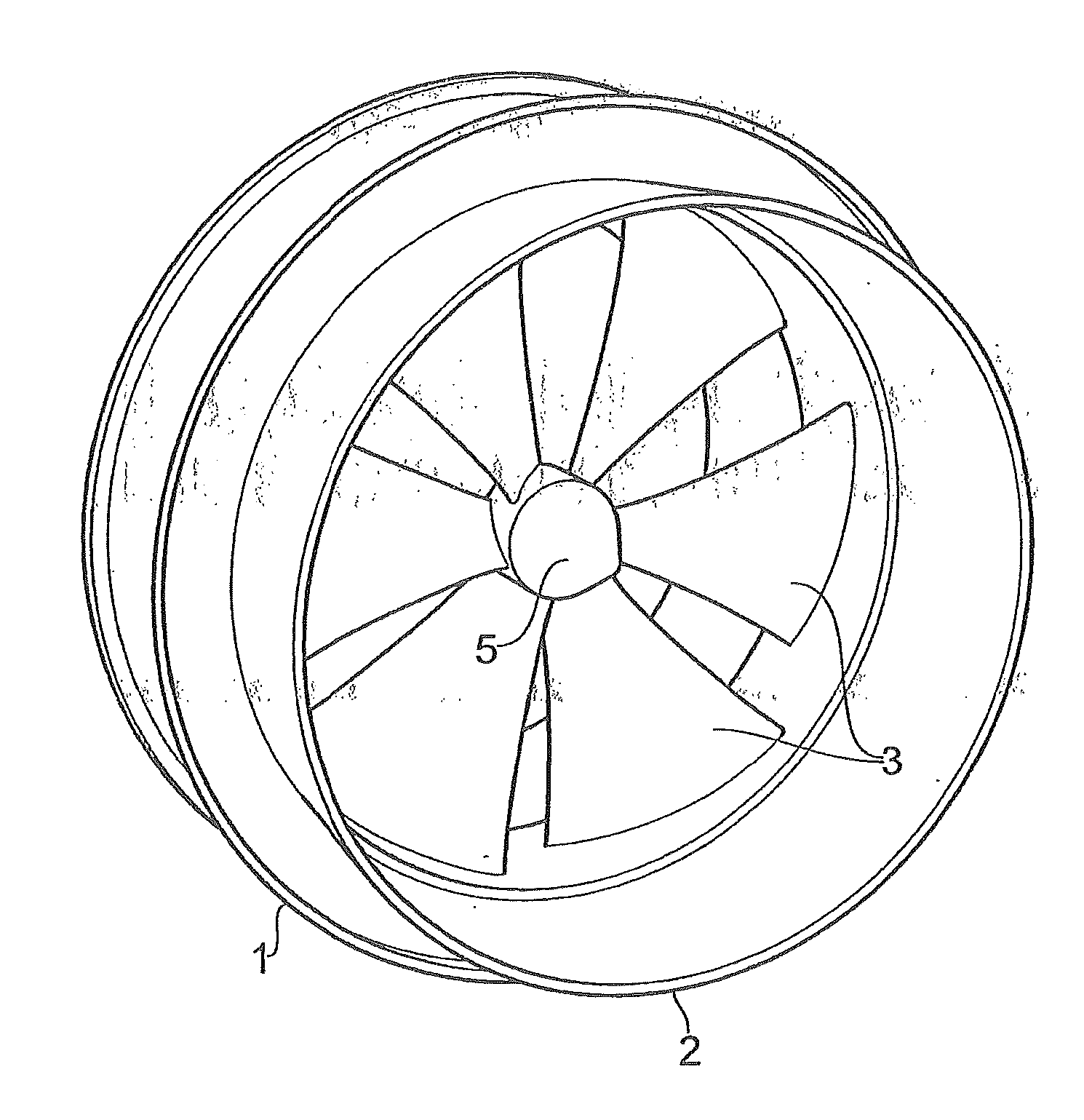
[0038] exist figure 1 A propeller unit according to the invention is shown in , wherein the propeller unit comprises an outer stationary casing 1 and a rotatable rotor casing 2 . The outer stationary casing 1 is securely mounted to a vessel (not shown) in a suitable manner such that the casing 1 forms a stationary unit with the vessel. A rotatable rotor casing 2 is internally mounted in the outer stationary casing 1 , wherein the rotor casing 2 includes a number of propeller blades 3 and a propeller hub 5 . The propeller blades 3 are firmly connected to the rotatable rotor casing 2 via the propeller hub 5 and the inner circumference of the rotatable rotor casing 2 . The outer diameter of the rotor housing 2 is smaller than the inner diameter of the stationary housing 1, and as a result, when the outer stationary housing 1 and the rotatable rotor housing 2 are assembled, there will be a difference between the outer circumference of the rotating rotor housing 2 and the inner ci...


PUM


Abstract

The present invention relates to a rim driven propeller unit for a vessel, where a number of permanent magnets are arranged round the propeller unit's rotatable rotor housing, comprising a number of propeller blades, and a number of permanent magnets round the propeller unit's external, stationary casing housing the rotatable rotor housing, where the permanent magnets round parts of the rotatable rotor housing and the external, stationary casing's circumference are provided located above one another with like polarity, while other parts of the rotatable rotor housing and the external, stationary casing are provided located facing one another with opposite polarity, whereby the rotor housing and the stationary casing are repelled by and attracted to one another respectively, thereby being prevented from coming into contact with one another.

Description

technical field [0001] The present invention relates to a support for a propeller unit for a watercraft, and more particularly the present invention relates to a support for a rim driven propeller unit, wherein the permanent magnets of the propeller unit are used as part of the support of the propeller unit . Arranged so that the permanent magnets forming the radial support of the propeller unit will interact with the axial bearing of the propeller unit, thereby forming together the axial and radial support of the propeller unit. [0002] The permanent magnets forming the radial support of the propeller unit interact with the axial bearing, thereby together forming the axial and radial support of the propeller unit. Background technique [0003] As the vessel moves through the mass of water, the propeller units of the vessel will experience greater or lesser loads. Due to waves and / or turbulence in the water, the mass of water passing through the propeller unit will create...

Claims


Application Information

Patent Timeline
Patent Type & Authority Applications(China)
IPC IPC(8): B63H1/14B63H5/14
CPCB63H1/16B63H21/17B63H2023/005F16C39/063F16C39/066F16C17/02F16C32/0425F16C2326/30B63H23/24H02K7/09
Inventor G.约翰森
Owner 康斯博海运公司
Why Eureka
Try Eureka