

Yarn winder
A winding device and yarn technology, which is applied in transportation and packaging, delivery of filamentous materials, thin material processing, etc., can solve the problems of yarn layer disorder, yarn end winding, etc., to avoid shortage and reduce power consumption , The effect of suppressing the consumption of storage capacity
- Summary
- Abstract
- Description
- Claims
- Application Information
AI Technical Summary
Problems solved by technology
Method used
Image

Examples
no. 1 approach
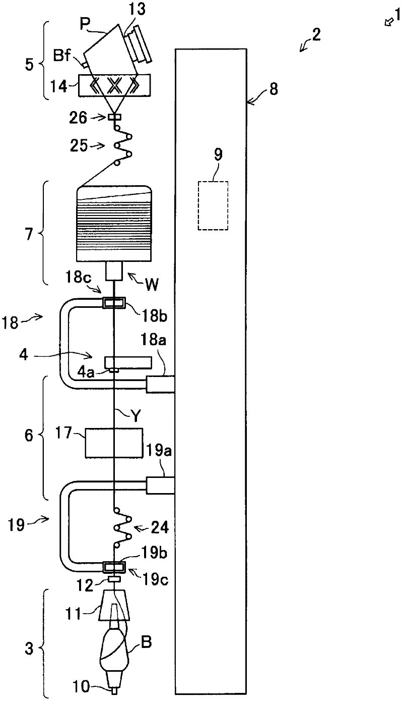
[0051] A yarn winding device according to a first embodiment of the present invention will be described below with reference to the drawings. Automatic winder 1 (fiber machinery) is made up of multiple such as 60 spindles etc. figure 1 The illustrated winding units 2 (yarn winding devices) are arranged side by side in the left-right direction of the paper.
[0052] The main configuration of each winding unit 2 includes: the yarn feeding part 3, which unwinds and supplies the spun yarn Y from the yarn feeding bobbin B; the yarn clearer 4 (yarn defect detection part), which can detect Yarn defects (yarn defects) of the spun yarn Y supplied from the yarn section 3; the winding section 5, which winds the spun yarn Y into a package P; Between the winding parts 5, when the bobbin of the above-mentioned yarn feeding bobbin B is replaced, when the yarn is cut or the yarn is broken when the yarn defect is detected by the yarn clearer 4, the yarn feeding part 3 side The spun yarn Y of...
no. 2 approach
[0130] Below, based on Figure 13 A second embodiment of the present invention will be described. Hereinafter, the difference between this embodiment and the above-mentioned first embodiment will be mainly described, and redundant description will be omitted.
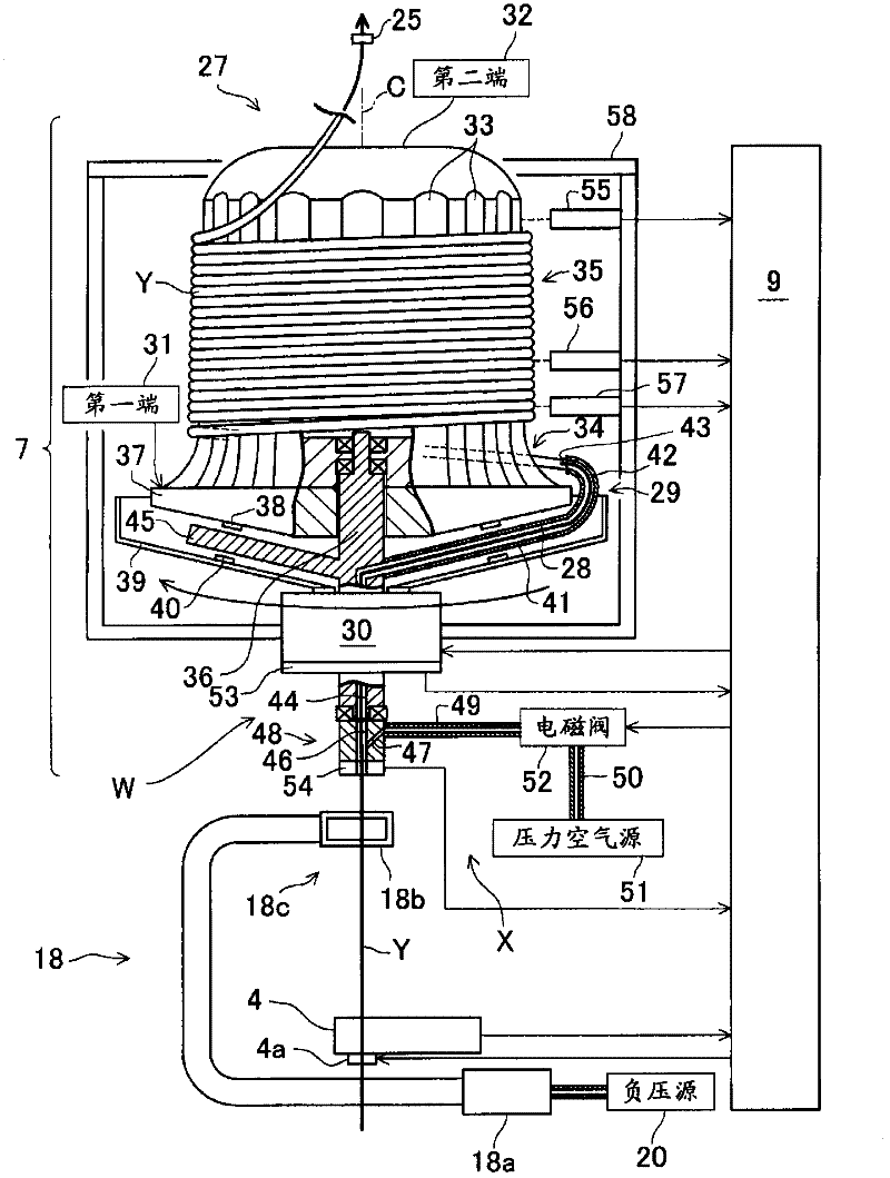
[0131] In the above first embodiment, if figure 2 As shown, the extraction sensor 54 is provided on the accumulator 7 . And in this embodiment, if Figure 13 As shown, the take-out sensor 54 is provided at the yarn splicing part 6 . Specifically, the take-out sensor 54 is provided on the upper transfer tube 18 of the yarn splicing unit 6 .
[0132] (Summarize)
[0133] (Technical Item 18)
[0134] As described above, in the present embodiment, the winding unit 2 is configured as follows. That is, the above-mentioned drawing sensor 54 is provided on the above-mentioned yarn splicing section 6 . According to such an arrangement, the above-mentioned drawing sensor 54 can detect that the yarn end of the spun yarn Y...
no. 3 approach
[0138] Below, based on Figure 14 A third embodiment of the present invention will be described. Hereinafter, the difference between this embodiment and the above-mentioned first embodiment will be mainly described, and redundant description will be omitted.
[0139] In the above first embodiment, if figure 2 As shown, the extraction sensor 54 is provided on the accumulator 7 . On the other hand, in this embodiment, the yarn clearer 4 described above is used as the take-off sensor 54 . In detail, as Figure 6 As shown, the upper side adapter tube 18 receives the yarn end of the textile yarn Y from the yarn end drawing mechanism W, and as shown in FIG. Figure 14 As shown, the upper side transfer tube 18 is rotated from top to bottom, and the spun yarn Y on the side of the accumulator 7 is placed on the yarn joining execution part 17 of the yarn joining part 6 to carry out the yarn joining realized by the yarn joining part 6, At this time, the presence of the spun yarn Y ...
PUM
 Abstract
Description
Claims
Application Information