

Light-emitting element
A technology of luminous body and light-emitting device, applied in the field of luminous body, to achieve the effect of preventing from burnout, low current consumption, and good connection
- Summary
- Abstract
- Description
- Claims
- Application Information
AI Technical Summary
Problems solved by technology
Method used
Image

Examples
Embodiment Construction
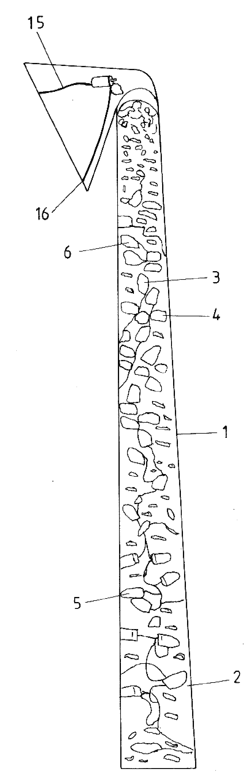
[0030] exist figure 1 A cylindrically shaped illuminant 1 is shown in . Its housing 2 is made of a transparent material, preferably glass or plastic, and has in its interior a multitude of light-emitting diodes, here more or less randomly assigned the reference numerals 3 , 4 , 5 , 6 . Due to the large number of light-emitting diodes 3, 4, 5, 6, etc., it is evident in this illustration that practically every shape of the luminous body is possible with the wiring pattern according to the invention, since the luminous body 1 is composed of a large number of small Unit composition with light emitting diodes. in accordance with figure 1 The present example is a tubular housing 2 which also has terminals 15 and 16 .
[0031] figure 2 With light-emitting diodes again more or less randomly assigned reference numerals 3, 4, 5, 6 it is shown figure 1 These LEDs are connected to each other through metal lines 17, 18, 19.
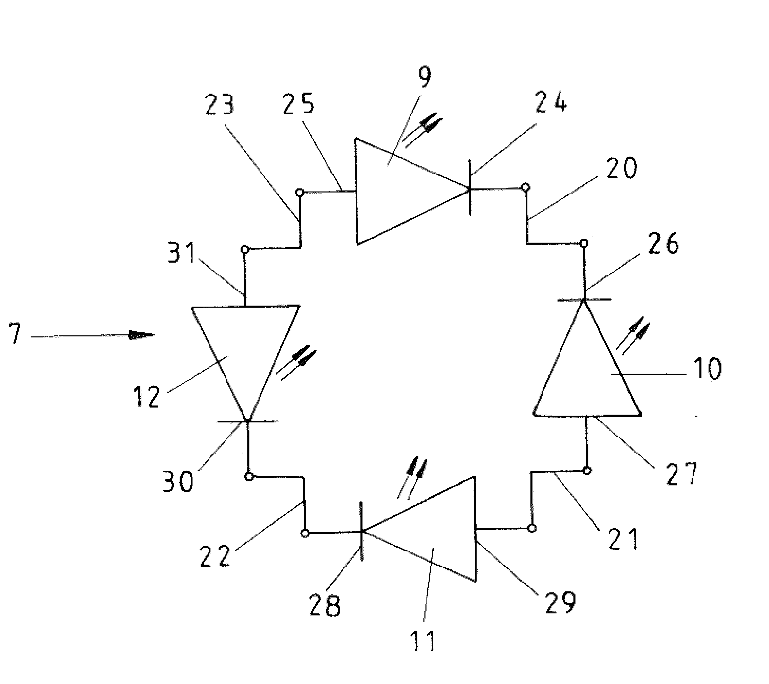
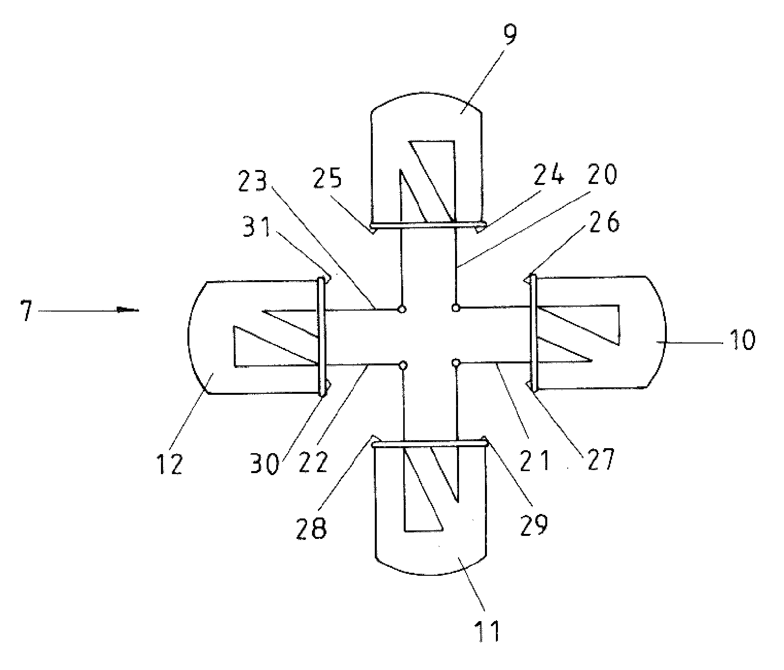
[0032] exist image 3 A unit 7 of diodes 9, 9', 10, 10' ...
PUM
 Abstract
Description
Claims
Application Information