
Threshing device of harvester

A technology of threshing device and harvester, which is applied in threshing equipment, agricultural machinery and implements, applications, etc., can solve the problems of shortened harvester life, increased grain loss rate, high threshing loss rate, etc., to achieve low threshing loss rate, threshing Fast speed and high threshing efficiency

Inactive Publication Date: 2015-06-17
俞军
View PDF6 Cites 0 Cited by
  • Summary
  • Abstract
  • Description
  • Claims
  • Application Information

AI Technical Summary

Problems solved by technology

If the crops to be harvested are relatively dry, they are easy to thresh during harvesting and the threshing loss rate is high. However, when the crops to be harvested are relatively wet and enter the threshing device, it is not easy to thresh or the threshing is incomplete, which will also increase the loss rate of grains; In actual production, due to the influence of various factors during harvesting, the crops are neither too dry nor wet during harvesting. Therefore, a harvester threshing device is developed to improve the threshing efficiency when the crops are relatively dry. Threshing is more complete when it is more humid, so as to solve the problem of high threshing loss rate without increasing the load of the threshing device and affecting the service life of the device, which has great social significance and economic benefits for the country and farmers
[0003] But present harvester threshing device mostly has poor threshing effect, especially when the described crops to be threshed are not dry enough, threshing rate is low; Some harvester threshing devices in the prior art are in order to strengthen threshing efficiency, and throughput (The stalk entering the threshing device is required to be no higher than 30cm), and the load on the machine is increased, which shortens the life of the harvester

Method used


Image

  • Threshing device of harvester
  • Threshing device of harvester
  • Threshing device of harvester

Examples


Embodiment 1

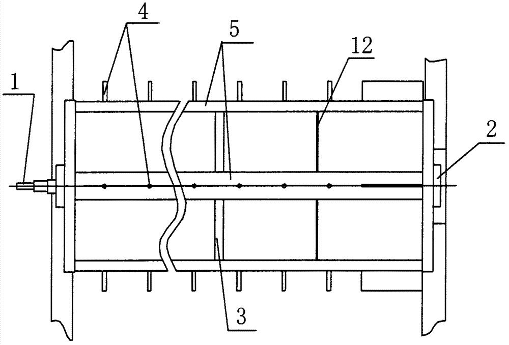
[0024] Embodiment 1 refers to appended figure 1 , 4 And 5, a harvester threshing device, comprising a main shaft 1, a bearing seat 2, a toothed nail 4, a reinforcement ring 3, a toothed nail fixing angle steel 5, a feed port 8, a discharge port 9, an upper cover 10 and a lower cover 11, It is characterized in that a threshing disc 12 is set on the main shaft 1 with the main shaft 1 as the center of the circle, the threshing disc 12 is fixedly connected with the nail fixed angle steel 5, and the distance between the threshing disc 12 and the right end of the feeding port 8 is 801 The distance is 440mm, and the distance from the right end 901 of the discharge port 9 is 80-100mm.

Embodiment 2

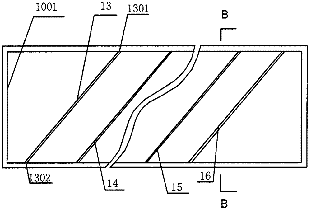
[0025] Embodiment 2 refers to the appended Figure 1-6 , a harvester threshing device, comprising a main shaft 1, a bearing seat 2, a toothed nail 4, a reinforcement ring 3, a toothed nail fixing angle steel 5, a feed port 8, a discharge port 9 and an upper cover 10, characterized in that: the main shaft 1 is the center of the circle. A threshing disc 12 is set on the main shaft 1. The threshing disc 12 is connected to the pinion fixing angle steel 5 by spot welding. The distance between the threshing disc 12 and the right end 801 of the feeding port 8 is 440mm , the distance from the right end 901 of the discharge port 9 is 80-100mm; the inner wall of the upper cover 10 is provided with a flat iron, the height of the flat iron is 20±2mm, the upper end 1301 of the flat iron 1 is 100-1200±2mm from the left side of the upper cover, and the lower end is 1302 The left side of the upper cover is 100190±2mm, the flat iron II 14, the flat iron III and the flat iron IV15 are arranged ...

Embodiment 3

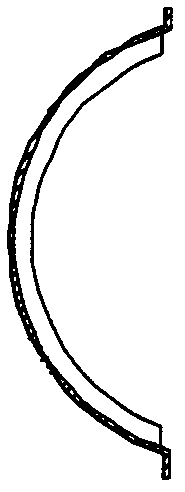
[0026] Embodiment 3 is with reference to attached Figure 2-8 , a harvester threshing device, comprising a main shaft 1, a bearing seat 2, a toothed nail 4, a reinforcement ring 3, a toothed nail fixing angle steel 5, a feed port 8, a discharge port 9 and an upper cover 10, characterized in that: the main shaft 1 is the center of the circle, and a threshing disc 12 is arranged on the main shaft 1, and the threshing disc 12 is fixedly connected with the nail fixing angle steel 5, and the distance between the threshing disc 12 and the right end 801 of the feeding port 8 is 440mm, and the distance The distance between the right end 901 of the discharge port 9 is 80-100mm; the inner wall of the upper cover 10 is provided with a flat iron, the height of the flat iron is 20±2mm, the upper end 1301 of the flat iron 1 is 1001200±2mm from the left side of the upper cover, and the lower end 1302 is 1302 from the upper cover Left side 100190±2mm, flat iron II 14, flat iron III and flat i...


PUM


Abstract

A threshing device of a harvester comprises a main shaft, a bearing seat, a toothed nail, a reinforcing ring, a toothed nail fixing angle steel, an input port, an output port and an upper cover. The threshing device is characterized in that a threshing round disc is arranged on the main shaft by taking the main shaft as the center of the round disc; the threshing round disc is fixedly connected with the toothed nail fixing angle steel; and the threshing round disc has a distance of 440mm from the right end of the input port, and a distance of 80 to 110mm from the right end of the output port. The threshing device of the harvester is safe and reliable, and has the advantages of high stability and high threshing speed. In addition, the threshing device has the following advantages: the threshing device has high threshing efficiency and can handle about 1Mu wetter crops in one hour; the threshing device can handle crops with the length of 40cm, and has high throughput, which is higher than that of the prior at by more than 30%; and the threshing device has low threshing loss rate (smaller than 1.18%), which is superior to the national standard (1.2%).

Description

technical field [0001] The invention relates to an agricultural machine, in particular to a small harvester threshing device. Background technique [0002] Harvesters are harvesting crops with stalks, such as wheat or rice, which need to be threshed. If the crops to be harvested are relatively dry, they are easy to thresh during harvesting and the threshing loss rate is high. However, when the crops to be harvested are relatively wet and enter the threshing device, it is not easy to thresh or the threshing is incomplete, which will also increase the loss rate of grains; In actual production, due to the influence of various factors during harvesting, the crops are neither too dry nor wet during harvesting. Therefore, a harvester threshing device is developed to improve the threshing efficiency when the crops are relatively dry. The threshing is more complete when it is more humid, so as to solve the problem of high threshing loss rate without increasing the load of the thres...

Claims


Application Information

Patent Timeline
Patent Type & Authority Patents(China)
IPC IPC(8): A01F12/22
Inventor 俞军
Owner 俞军
Learn More