Bidirectional water flow channel

A flow channel and water flow technology, applied in the field of two-way water flow channels, can solve the problems of difficult control of manufacturing precision, easy aging of elastic diaphragms, and affecting service life, etc., and achieve strong anti-blocking, low production cost, and not easy to aging effects

Inactive Publication Date: 2012-07-11
XIAN UNIV OF TECH
View PDF4 Cites 6 Cited by
  • Summary
  • Abstract
  • Description
  • Claims
  • Application Information

AI Technical Summary

Problems solved by technology

Turbulent flow labyrinth flow channel, such as the technical solutions disclosed in patent texts such as CN201199834, CN201632346, CN201871438, CN201346503 and CN201192667, its working principle is: when pressurized water flows through a curved flow channel, turbulent flow is formed, resulting in The vortex will cause a large local head loss. In order to eliminate the excess pressure at the drip irrigation emitter, a series of curved flow channels are connected end to end to form a turbulent labyrinth flow channel. The flow index of this type of flow channel is between 0.5 and 0.7, when the working pressure of the dripper changes, the change of the output flow of the dripper is small, its manufacturing cost is low, and its service life is long, but due to the small size of the flow channel section, its anti-blocking performance is poor The channel is long, and the manufacturing precision is not easy to control
Pressure-compensated flow channels, such as the technical solutions disclosed in patent documents such as CN2648806, CN201446021, CN2660883, and CN200987311, all work on the principle that when pressurized water flows through the pressure-compensated flow channel, the water pressure acts on the flow channel. On the elastic diaphragm, the water pressure is different, and the deformation of the elastic diaphragm is different, so as to adjust the size of the cross section of the flow channel to achieve the purpose of energy dissipation and decompression. The flow index of this type of flow channel is about 0.1, when When the working pressure of the dripper changes greatly, the flow rate of the dripper changes very little; however, due to the elastic diaphragm device inside the flow channel, its production cost is relatively high. In the harsh environment of the farm field, the elastic diaphragm is easy to age, which affects Its service life is long, and at the same time, due to the small cross-section of the flow channel, the flow channel is easy to block

Method used


Image

  • Bidirectional water flow channel
  • Bidirectional water flow channel
  • Bidirectional water flow channel

Examples


Embodiment 1

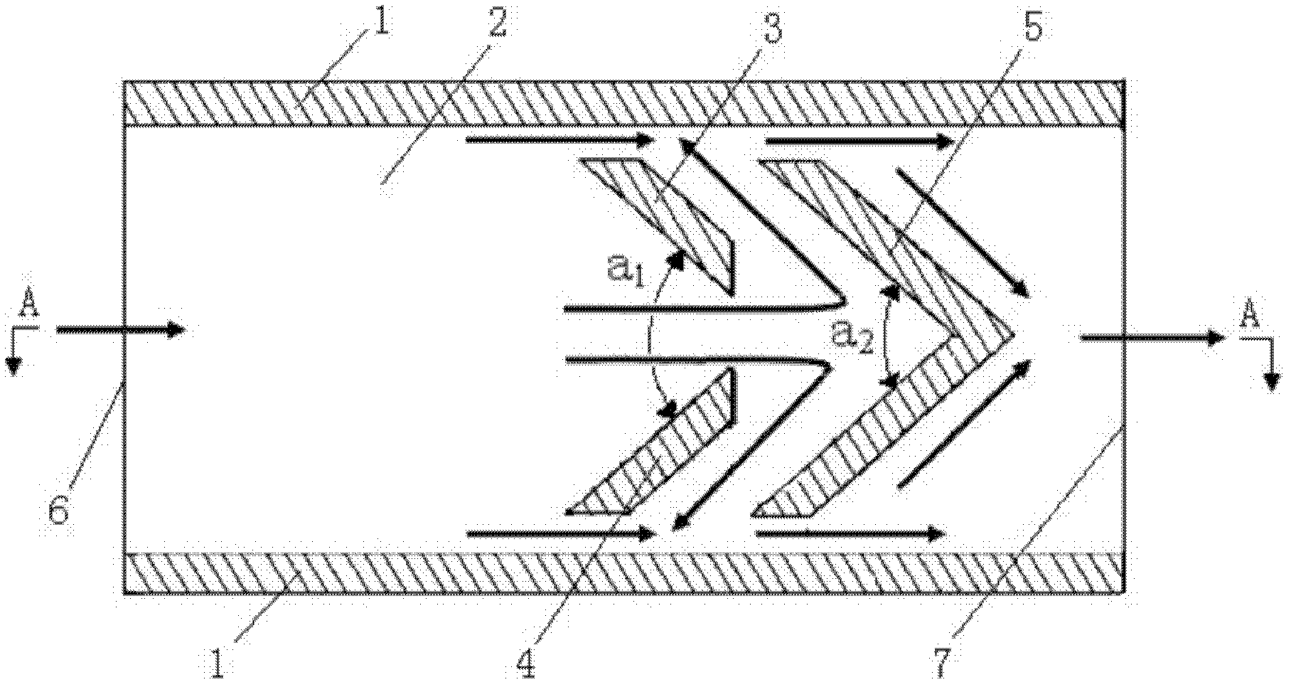
[0020] like figure 1 and figure 2 As shown, the two-way water flow channel of the present invention includes a rectangular bottom plate 2 , the front end of the bottom plate 2 is opened and serves as a water inlet 6 , and the rear end of the bottom plate 2 is opened and used as a water outlet 7 . The left and right sides of the bottom plate 2 are both symmetrical and parallel with a water-retaining outer wall 1 . On the bottom plate 2 and between the two water-retaining outer walls 1 , a first water diversion plate 3 , a second water diversion plate 4 and a water retaining member 5 are arranged. Wherein, the first water diversion plate 3 and the second water diversion plate 4 are spaced apart and symmetrically arranged left and right, and form a figure-eight water diversion piece. The gap between the first water diversion plate 3 and the second water diversion plate 4 is used as the water passing hole of the water diversion member. The water retaining member 5 is V-shaped ...

Embodiment 2

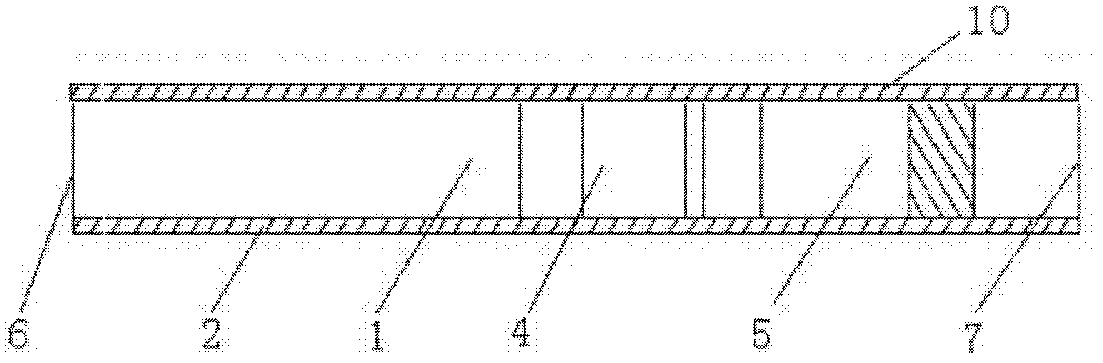
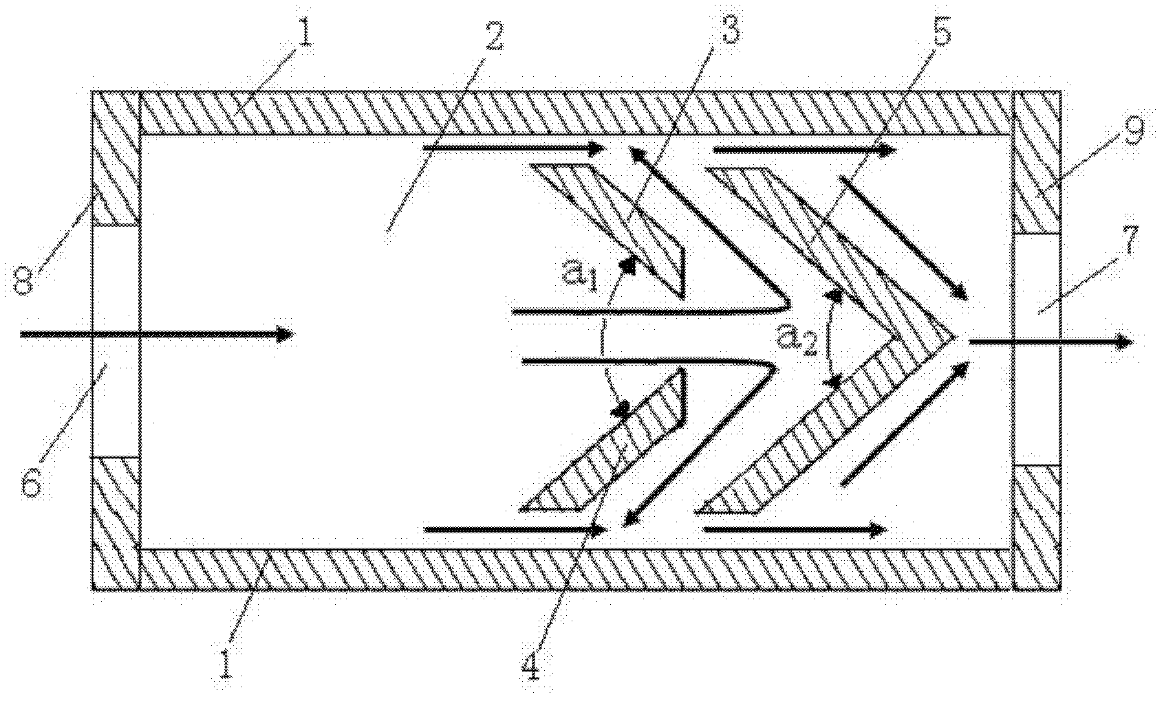
[0027] like image 3 As shown, the difference between this embodiment and Embodiment 1 is: a front baffle 8 is installed on the front end of the base plate 2, the water inlet 6 is opened on the front baffle 8, and a rear baffle 9 is installed on the rear end of the base plate 2. Water outlet 7 is opened on the tailgate 9. Wherein, there is one water inlet 6 and one water outlet 7 , and they are located on the center line of the bottom plate 2 . At this time, the top plate 10, the bottom plate 2, the front baffle plate 8, the rear baffle plate 9, the two water retaining outer walls 1, the first water diversion plate 3, the second water diversion plate 4 and the water retaining member 5 are all integral structures . The number of water inlets 6 can also be set to be multiple, and they are evenly distributed on the front baffle 8 with the center line of the bottom plate 2 as a line of symmetry, and the number and distribution of water outlets 7 are consistent with the water inl...


PUM


Abstract

The invention discloses a bidirectional water flow channel, which comprises a base plate, wherein a water inlet is arranged at the front section of the base plate; a water outlet is arranged at the rear section of the base plate; a water baffle outer side wall is symmetrically arranged at the left side and the right side of the base plate in parallel; a first water dividing plate, a second water dividing plate and a water baffle piece are arranged on the base plate and between the two water baffle outer side walls; the first water dividing plate and the second water dividing plate are symmetrically arranged left and right at intervals to form a splayed water dividing piece; the water baffle piece is V-shaped and is arranged at the rear part of the water dividing piece at intervals; the openings of the water dividing piece and the water baffle piece both face the direction of the water inlet; water flowing channels are formed between the outer wing of the first water dividing plate and the outer side wall of the water baffle plate, between the outer wing of the second water dividing plate and the outer side wall of the water baffle plate, and between the outer ring of the water baffle piece and the outer side wall of the water baffle plate; and the symmetric lines of the water dividing piece and the water baffle piece are both coaxial with the center line of the base plate. The bidirectional water flow channel is simple in structure, stable in flow, strong in anti-blocking performance, small in manufacturing deviation, low in production cost and long in service life.

Description

technical field [0001] The invention belongs to the technical field of drip irrigation in agricultural and forestry irrigation, and in particular relates to a bidirectional water flow channel applied in a drip irrigation dispenser. Background technique [0002] Drip irrigation is an advanced water-saving irrigation technology. The drip irrigation emitter is one of the most important components in the drip irrigation system. Its function is to dissipate the energy of the pressurized water flow through the internal flow channel, so that the water flow drips into the soil near the root layer of the crop at a uniform and stable low flow rate. Due to the influence of the water head loss of the pipe network and the ground height difference in the drip irrigation system, the pressure of the pipe network is different at different places. The function of the dripper is to generate local head loss through its internal flow channel and eliminate the excess water pressure at the entranc...

Claims


Application Information

Patent Timeline
Patent Type & Authority Applications(China)
IPC IPC(8): A01G25/02
Inventor 白丹宋立勋郭霖
Owner XIAN UNIV OF TECH
Why Eureka
Try Eureka