
Grinding roller pressurization device for vertical mill

A technology of pressurizing device and grinding roller, which is applied in the direction of grain processing, etc., and can solve the problems of overall increase in the manufacturing cost of the mill shell, increased component load, leakage and increased wear, etc.

Active Publication Date: 2014-02-12
王华业
View PDF3 Cites 0 Cited by
  • Summary
  • Abstract
  • Description
  • Claims
  • Application Information

AI Technical Summary

Problems solved by technology

The main defect of this vertical roller pressing device is:
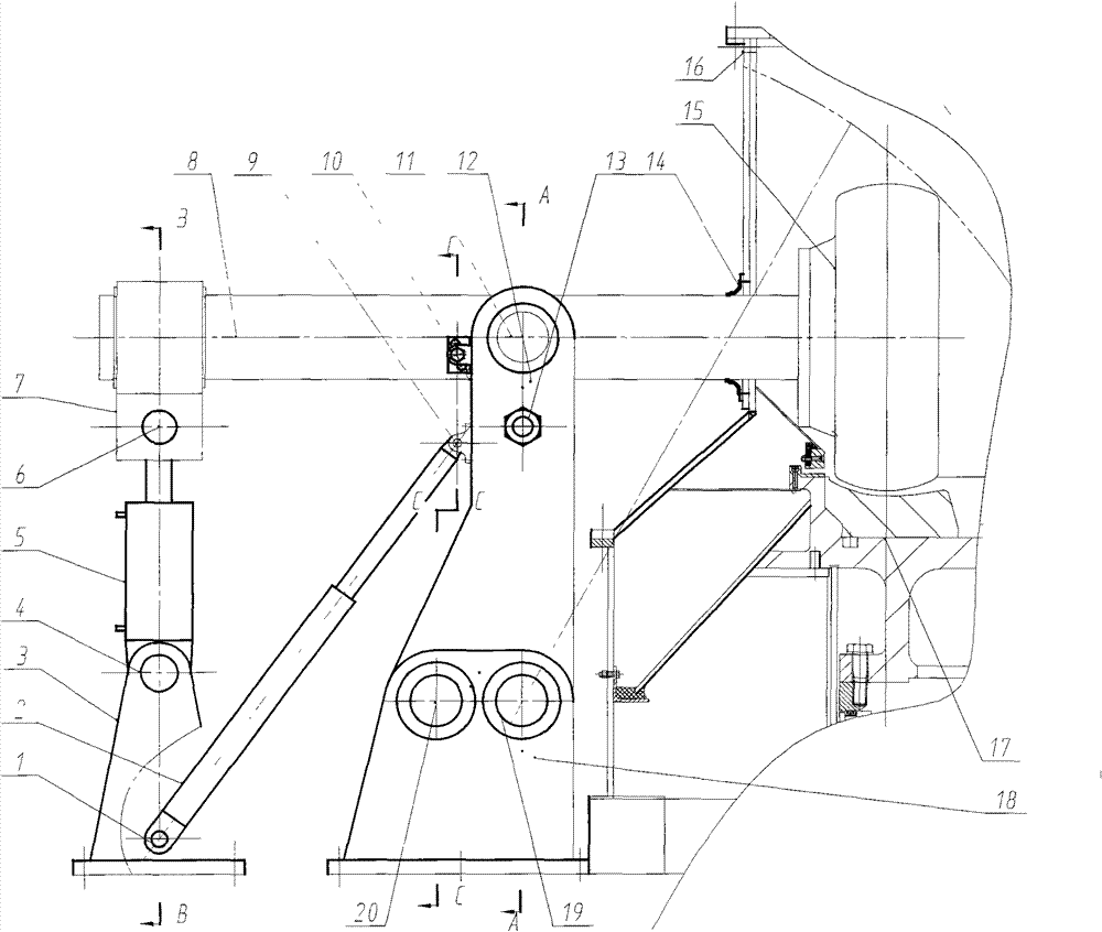
[0003] 1) In order to make the vertical downward pressure on the grinding roller, the hydraulic tension applied to the "7"-shaped lever arm is usually oblique to the arm, so part of the hydraulic force is lost in useless work and increases the component load; 2) Applying When there is a rod chamber working under tension, the oil supply pressure will increase by 30% year-on-year, and the probability of leakage and wear will increase; 3) The pressurizing device is hinged on the mill shell, which increases the overall manufacturing cost of the mill shell; 4) The grinding roller maintenance and surfacing welding must be turned out of the mill, the grinding roller rotates around the hinge shaft, the grinding door must be higher, and the turning space above the grinding table must be larger

Method used


Image

  • Grinding roller pressurization device for vertical mill
  • Grinding roller pressurization device for vertical mill
  • Grinding roller pressurization device for vertical mill

Examples


Embodiment Construction

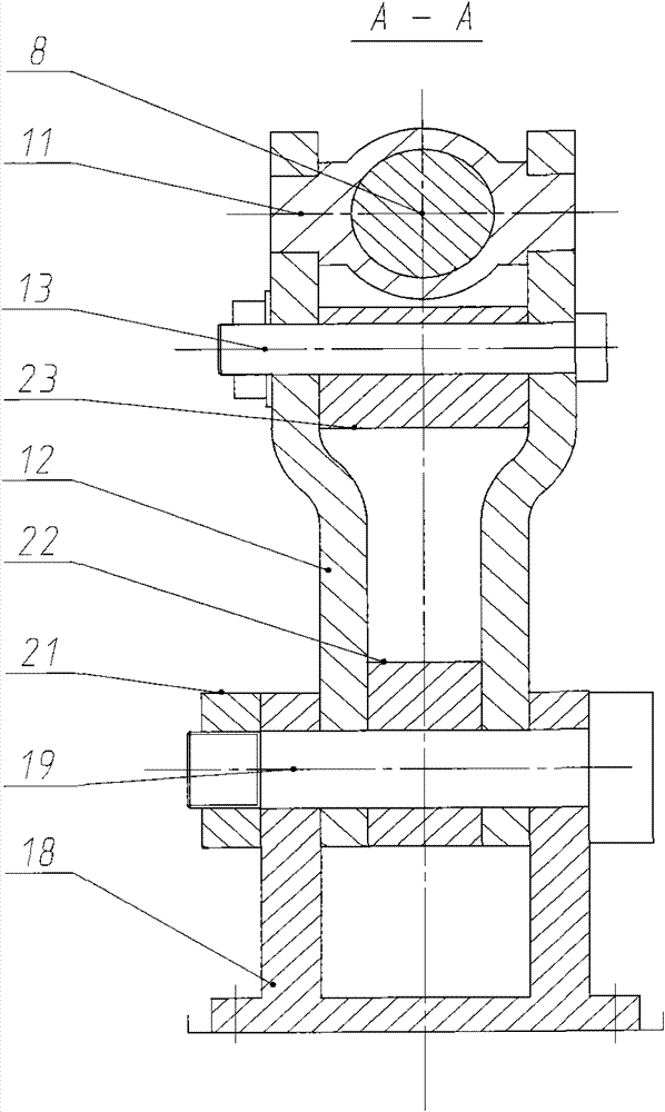
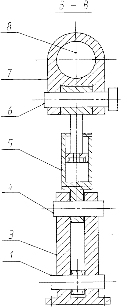
[0030] When grinding materials, pressurized oil is fed into the rodless chamber of pressurized oil cylinder 5, and the piston rod head pushes pressurized rod 8 through hinge support shaft B6 and pressurized rod sleeve 7. At this time, the locking stud 27 of locking device 10 Unscrew the screw hole plate 26, disengage from the pin hole plate 25, the pressure rod rotates around the axis of the pressure rod support pin shaft 11 supported on the pressure rod support plate 12; the grinding roller 15 assembled with the pressure rod through the bearing group Under the action of the hinge of the supporting pin of the pressing bar, it is pressed towards the grinding disc 17, and the material rotating with the grinding disc can be ground in the extrusion channel between the grinding roller and the grinding disc. The support plate hinge shaft 19 and the support plate locating pin 20 are jointly loaded; and are transmitted to the foundation through the pressure bar support seat 18 connecte...


PUM


Abstract

The invention discloses a grinding roller pressurization device for a vertical mill. The grinding roller pressurization device for the vertical mill comprises a compression roller component, a supporting device, a pressurization oil cylinder and an overhaul oil cylinder. The invention aims to provide the grinding roller pressurization device for the vertical mill which can overcome the disadvantages. During grinding, the hydraulic thrust vertically acts on a grinding roller pressurization rod, and oil flows into an operating travel rodless cavity to reduce oil supply pressure, hydraulic leakage and wear, and idle work loss of diagonal tension and member loads; and according to different motion requirements of grinding working condition and overhaul working condition on a grinding roller, the pressurization rod and a pressurization rod supporting plate are in hinged connection and in rigid connection, the pressurization rod supporting plate and a pressurization rod supporting base are in hinged connection and rigid connection, and the two modes correspond to each other in a staggered way, so that the load requirements of the supporting device during grinding are met, the turning space when the grinding roller is overhauled is also reduced, and the manufacturing cost of the vertical mill is reduced. The invention belongs to the field of technical equipment of powder engineering, and is applied to grinding materials of vertical mills.

Description

technical field [0001] The invention belongs to the technical field of powder engineering, and is applied to a vertical mill for crushing powdery materials. Background technique [0002] Most of the vertical grinding roller pressurizing devices in the current technology are made of a "7" shaped lever, one end is connected to the grinding roller through a bearing assembly, and the other end is hingedly connected to the extending end of the piston rod of the hydraulic cylinder. The frame of the vertical mill shell is hinged and connected, and when the hydraulically driven piston rod pulls one end of the "7"-shaped lever, the grinding roller at the other end acts on the hinged shaft at the apex of the "7"-shaped corner to roll the material on the grinding table of the vertical mill. . The main defect of this vertical roller pressing device is: [0003] 1) In order to make the vertical downward pressure on the grinding roller, the hydraulic tension applied to the "7"-shaped le...

Claims


Application Information

Patent Timeline
Patent Type & Authority Patents(China)
IPC IPC(8): B02C15/06
Inventor 王华业
Owner 王华业
Learn More