
Laser Material Processing Device With Prism

A laser material, polygon mirror technology, applied in laser welding equipment, metal processing equipment, laser optical equipment and other directions, can solve the problem of flexible selection and other problems, achieve good processing results, improve efficiency, and improve product quality.

Inactive Publication Date: 2012-07-11
TRUMPF LASERSYST FOR SEMICON MFG
View PDF6 Cites 4 Cited by
  • Summary
  • Abstract
  • Description
  • Claims
  • Application Information

AI Technical Summary

Problems solved by technology

Therefore, all flexible choices of line spacing are not achievable

Method used


Image

  • Laser Material Processing Device With Prism
  • Laser Material Processing Device With Prism
  • Laser Material Processing Device With Prism

Examples


Embodiment Construction

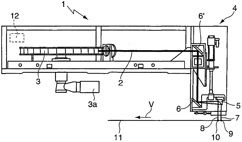
[0027] figure 1 A laser material processing device 1 for a so-called laser scribing device is shown, which has a rotatably mounted polygon mirror 3 which deflects a laser beam 2 generated by a laser source (not shown) onto a focusing unit 4 . The polygon mirror 3 has drive means 3a in the form of a servo motor in order to drive the polygon mirror 3 with a desired rotational speed.

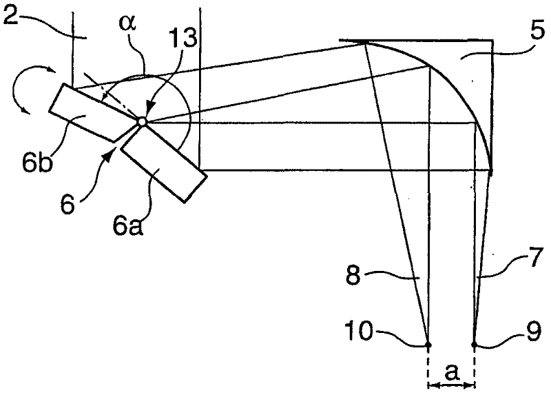
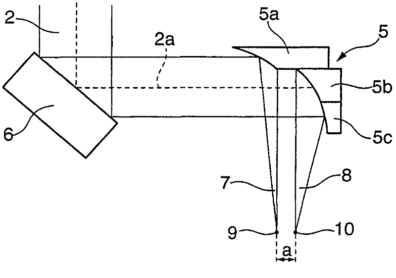
[0028] The focusing unit 4 comprises a first plane deflection mirror 6' which deflects the laser beam 2 by 90° onto a second plane deflection mirror 6. The laser beam 2 is deflected by means of a second plane deflection mirror 6 onto a focusing means for the laser beam 2 in the form of a focusing mirror 5 . here according to the figure 2 The light splitting principle described in detail in is split by the second deflection mirror 6 . It is to be noted here that the first deflecting mirror 6' can optionally also be used as a beam splitter of this type, or that two deflecting mirrors 6, 6' can be...


PUM


Abstract

The present invention relates to a laser material processing device (1) which comprises the following components: the prism (3) which is rotatably supported for deflecting a laser beam (2), and a focusing unit (4) which is provided at the downstream part in the optical path and is provided with a focusing device (5). The focusing device is used for focusing the laser beam (2) which is deflected to the focusing unit (4) by the prism (3) to a workpiece (11) to be processed. According to the invention, the focusing unit (4) is provided with at least one light splitter (5,6,6'). The light splitter is used for splitting the deflected laser beam (2) to at least two splitted light beams (7,8) for generating at least two focuses (9,10) on the workpiece (11). Furthermore the light splitters (5,6,6') are constructed for generating a variable distance (a) between the focuses (9,10) on the workpiece (11).

Description

technical field [0001] The invention relates to a laser material processing device with a rotatably mounted polygon mirror for deflecting a laser beam and with a downstream focusing unit in the beam path, which has a focus unit for deflecting the laser beam from the polygon mirror onto the focusing unit The laser beam is focused on the focusing device on the workpiece to be processed. Background technique [0002] A device of this type is known, for example, from US 4,099,830. The device described there for processing plastic running tracks has a polygon mirror mounted rotatably about two axes, wherein a laser beam is projected as a linear focal point onto the workpiece via a focusing unit. In order to generate a linear focus, the laser beam is deflected or imaged in different ways using cylindrical lenses in two directions extending perpendicularly to the direction of propagation. The lens arranged downstream of the polygon mirror in the optical path serves on the one han...

Claims


Application Information

Patent Timeline
Patent Type & Authority Applications(China)
IPC IPC(8): B23K26/067
CPCH01S3/005B23K26/0676G02B26/12B23K26/0815B23K26/0821
Inventor M·胡翁克J·米勒
Owner TRUMPF LASERSYST FOR SEMICON MFG
Learn More