Receiving device for laser marking machine

A technology of laser marking machine and material receiving device, which is applied to printing devices, typewriters, printing and other directions, can solve the problems of low efficiency, high labor intensity, and damage to workpieces by missed hands, and achieves the effect of high efficiency and simple structure.

Inactive Publication Date: 2012-07-11
SIP GOLDWAY TECH
View PDF5 Cites 6 Cited by
  • Summary
  • Abstract
  • Description
  • Claims
  • Application Information

AI Technical Summary

Problems solved by technology

This processing method is inefficient, labor-intensive, and prone to accidental damage to the workpiece

Method used


Image

  • Receiving device for laser marking machine
  • Receiving device for laser marking machine

Examples


Embodiment Construction

[0010] Specific embodiments of the present invention will be further described in detail below.

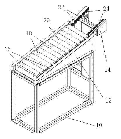
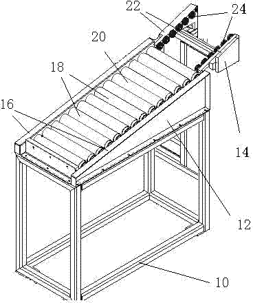
[0011] Such as figure 1 As shown, a material receiving device for a laser marking machine according to the present invention includes a bracket 10 on which an unloading device 12 and a transition device 14 are arranged. The unloading device 12 includes two parallel right-angled triangular side plates 16 , and the right-angle sides of the side plates 16 of the unloading device 12 are arranged on the support 10 . Several rotating shafts 18 are parallel to each other, and the two ends of the rotating shafts 18 are respectively arranged on the hypotenuses of the side plates 16 to form a inclined blanking surface 20 .

[0012] The transition device 14 includes two side plates 22 parallel to each other. One end of the side plate 22 of the transition device 14 is connected to the belt transmission device (not shown) of the laser marking machine, and the other end is connected to the hig...


PUM


Abstract

The invention discloses a receiving device for a laser marking machine. The receiving device comprises a bracket, and is characterized in that: a discharging device is arranged on the bracket; an inclined discharging surface is formed on the discharging device and consists of a plurality of parallel rotating shafts; and a higher end of the discharging surface is connected with the laser marking machine. The receiving device of the laser marking machine is connected with a belt conveying device of the laser marking machine through a roller and the rotating shafts on an inclined surface, a machined workpiece falls naturally along the receiving device under the action of gravity, and the lowest end of the receiving device can be connected with the belt conveying device or a container for storing workpieces, so that an automatic receiving process can be realized. The receiving device for the laser marking machine has the advantages of simple structure, high efficiency and the like.

Description

technical field [0001] The invention relates to a laser marking machine used for automobile clutches, especially a material receiving device thereof. Background technique [0002] The clutch of the car is a circular structure, and it usually needs to be engraved with a laser to mark the manufacturer and specification. This work is usually done by a laser marking machine. The feeding device of the laser marking machine usually uses a belt transmission device to send the clutch to the bottom of the laser for marking operations. Then it is sent to the receiving position of the laser marking machine by the belt transmission device, and it is taken away manually. This processing method is inefficient, labor-intensive, and prone to accidental damage to the workpiece. [0003] Contents of the invention [0004] The present invention provides a solution to the above problems, and provides a material receiving device for a laser marking machine with a simple structure and high e...

Claims


Application Information

Patent Timeline
Patent Type & Authority Applications(China)
IPC IPC(8): B41J13/00B41J3/407
Inventor 沈皓然
Owner SIP GOLDWAY TECH
Why Eureka
Try Eureka