Wheeled crane and moveable counterweight component thereof

A wheeled crane and movable counterweight technology, applied in cranes and other directions, can solve the problems of time-consuming installation of the counterweight body, potential safety hazards for ground staff, and difficulty in precise positioning, so as to save manual collaboration and ensure labor. Safety and work efficiency

Inactive Publication Date: 2012-07-11
XUZHOU HEAVY MASCH CO LTD
View PDF9 Cites 2 Cited by
  • Summary
  • Abstract
  • Description
  • Claims
  • Application Information

AI Technical Summary

Problems solved by technology

[0006] The installation of the above-mentioned counterweight body is mainly based on the installation experience of the operator and the cooperation of the ground personnel. Due to the limitation of the field of view, the operator cannot see the counterweight positioning hole at the bottom of the movable counterweight and the counterweight on the frame. Whether the repositioning block is consistent can only be operated vaguely by feeling, and the positioning and placement of the movable counterweight needs to be completed through multiple trial installations, which makes the installation process of the counterweight body very time-consuming; at the same time, when placing the counterweight body During the process, due to the influence of the wind force and the inertia of the counterweight itself, the counterweight body will swing back and forth, making it difficult to accurately locate. According to the traditional placement method, manual coordination of ground personnel is generally required for positioning. Therefore, the entire installation The process has brought great safety hazards to the ground staff

Method used


Image

  • Wheeled crane and moveable counterweight component thereof
  • Wheeled crane and moveable counterweight component thereof
  • Wheeled crane and moveable counterweight component thereof

Examples


Embodiment Construction

[0029] The core of the present invention is to provide a movable counterweight assembly for wheeled cranes, which is relatively convenient to install, thereby reducing installation time and improving work efficiency; at the same time, it does not need manual assistance in positioning during installation, ensuring safe operation higher. Another core of the present invention is to provide a wheeled crane including the above movable counterweight assembly.

[0030] In order to enable those skilled in the art to better understand the technical solutions of the present invention, the present invention will be further described in detail below in conjunction with the accompanying drawings and specific embodiments.

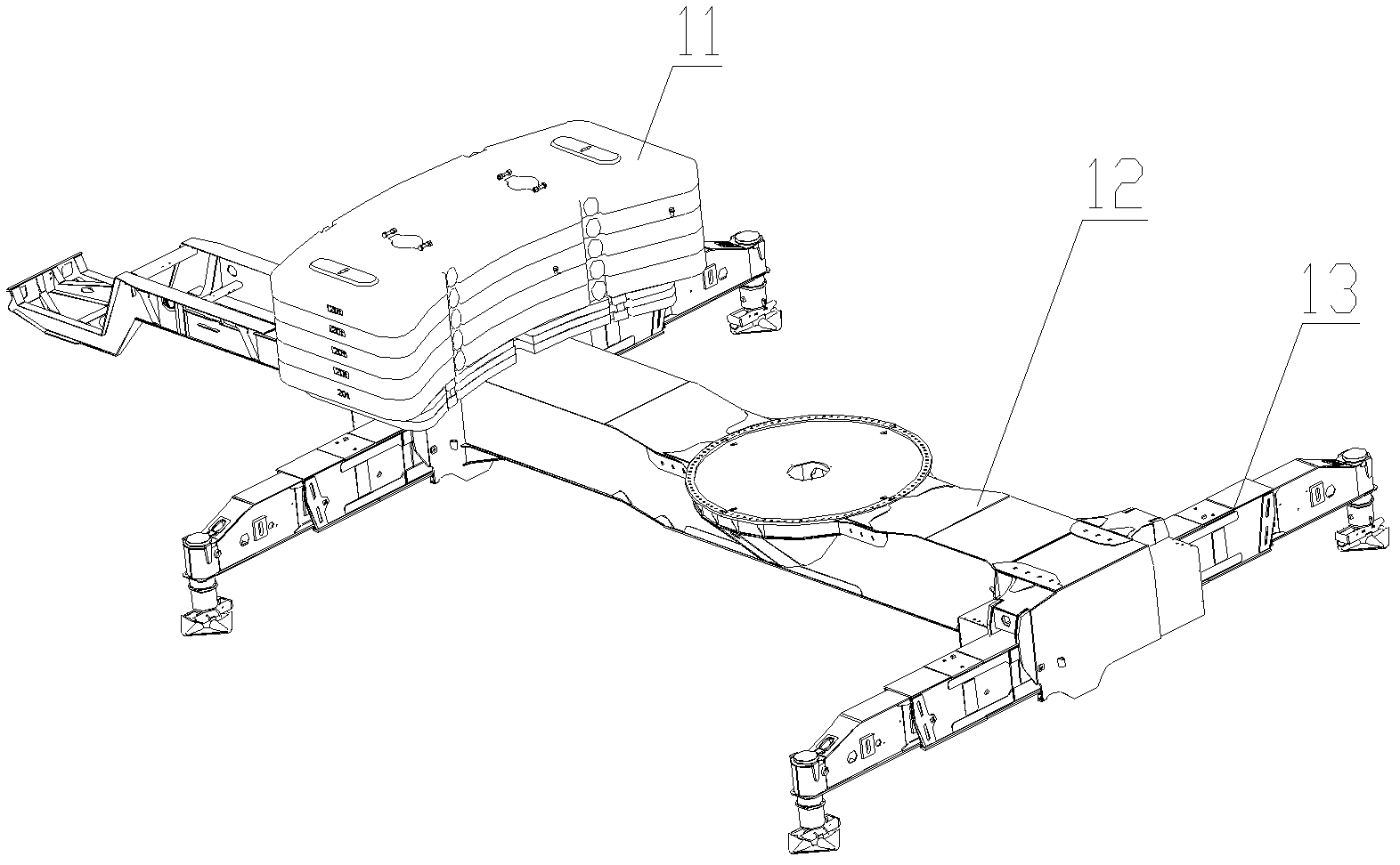
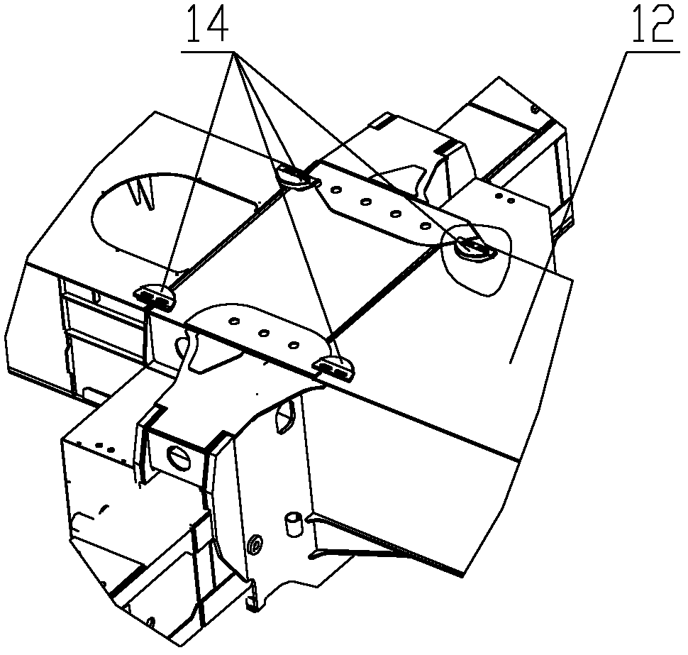
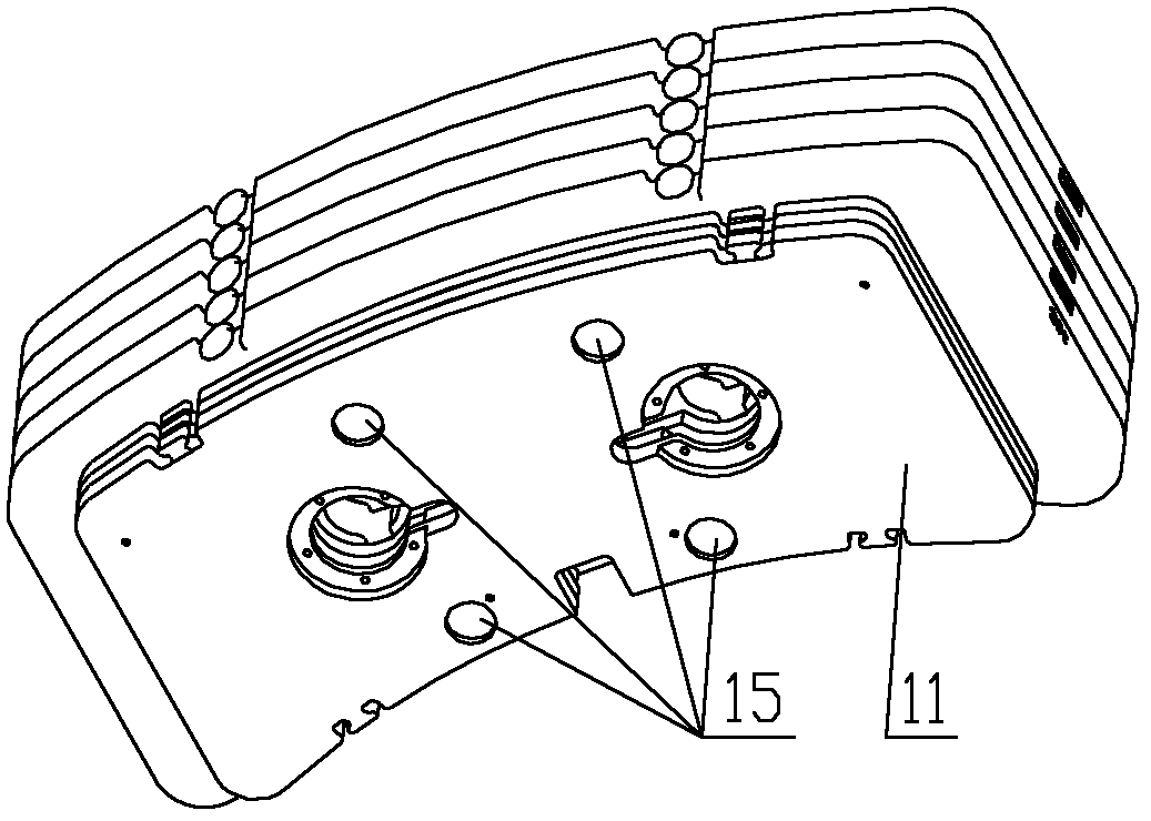
[0031] Please refer to Figure 4 , Figure 5 as well as Figure 6 , Figure 4 A structural schematic diagram of a specific embodiment of the movable counterweight assembly provided by the present invention; Figure 5 for Figure 4 Schematic diagram of the structure...


PUM


Abstract

The invention discloses a moveable counterweight component of a wheeled crane. The moveable counterweight component of the wheeled crane comprises a counterweight body (26) and a positioning mechanism, wherein the counterweight body (26) is arranged on a vehicle frame (21) of the wheeled crane through the positioning mechanism. The moveable counterweight component of the wheeled crane also comprises a guide mechanism, wherein the guide mechanism (22) further comprises a first guide part and a second guide part; the second guide part is connected with the first guide part in a sliding and detachable manner; the first guide part is arranged on the vehicle frame (21) and extends outwards relative to the vehicle frame (21); the second guide part is arranged on the outer surface of the counterweight body (26); and the sliding direction of the two guide parts is as same as the assembling direction of the counterweight body (26). The moveable counterweight component has short operating time during assembling, effectively avoids potential hazards to workers when the counterweight is arranged and guarantees labor safety. The invention also discloses the wheeled crane comprising the moveable counterweight component.

Description

technical field [0001] The invention relates to the field of engineering machinery, in particular to a movable counterweight assembly for a wheeled crane. The present invention also relates to a wheeled crane comprising the above movable counterweight assembly. Background technique [0002] With the rapid development of my country's economic construction, the market's demand for construction machinery, especially various cranes, is increasing. The increasing operating height and lifting tonnage of cranes make the crane's tipping moment larger during operation. , which brings many potential dangers to the lifting operation; in order to ensure the safety of the crane and avoid tipping when the crane is hoisted, it is necessary to install a counterweight on the crane frame. The counterweight is generally a block structure of cast iron material. When the crane When performing hoisting operations, it is hung at the tail of the crane, and the gravity moment of the counterweight is ...

Claims


Application Information

Patent Timeline
Patent Type & Authority Applications(China)
IPC IPC(8): B66C23/74
Inventor 李忠杰付小辉崔书文李丽梁静文
Owner XUZHOU HEAVY MASCH CO LTD
Why Eureka
Try Eureka