Hydraulic rope unreeling control system, hydraulic rope reeling control system and crane

A hydraulic control system and rope receiving technology, which is applied in the rope releasing hydraulic control system, rope receiving hydraulic control system and crane fields, can solve the problems of negative impact on the service life of the steel wire rope, small load and high cost of the hydraulic motor, and avoid chaos Rope, convenient debugging, cost-saving effect

Active Publication Date: 2012-07-11
ZOOMLION HEAVY IND CO LTD
View PDF7 Cites 16 Cited by
  • Summary
  • Abstract
  • Description
  • Claims
  • Application Information

AI Technical Summary

Problems solved by technology

[0002] The current cranes require multiple hoists to act in concert. When these hoists take in or release the rope, because the length of the rope, the size of the pulley, and the position of the wire rope on the jib are different, the actions between the multiple hoists are nonlinear, so It is difficult to control multiple hoists to achieve synchronization
[0003] If the winding and unwinding ropes of multiple hoists are not synchronized, the following problems will be caused: the hoist with a relatively slow unwinding speed will bear a large load, and the steel wire rope will be in an over-tensioned state, which will have a negative impact on the service life of the steel wire rope and the service life of the hydraulic motor. Negative impact: The winch with a relatively fast rope release speed will bear a small load, or even no load, and the wire rope is in a loose state. If it is too loose, the rope will be disordered, which will seriously affect the normal operation of the crane
[0004] In the prior art, the crane adopts a closed-loop control method to realize the synchronization of multiple hoists. This control method requires the use of controllers, sensors and other devices, which is costly and can only achieve simple approximate linear synchronization. It is difficult to debug.

Method used


Image

  • Hydraulic rope unreeling control system, hydraulic rope reeling control system and crane
  • Hydraulic rope unreeling control system, hydraulic rope reeling control system and crane
  • Hydraulic rope unreeling control system, hydraulic rope reeling control system and crane

Examples


Embodiment Construction

[0024] The present invention will be described in detail below in conjunction with the accompanying drawings and embodiments.

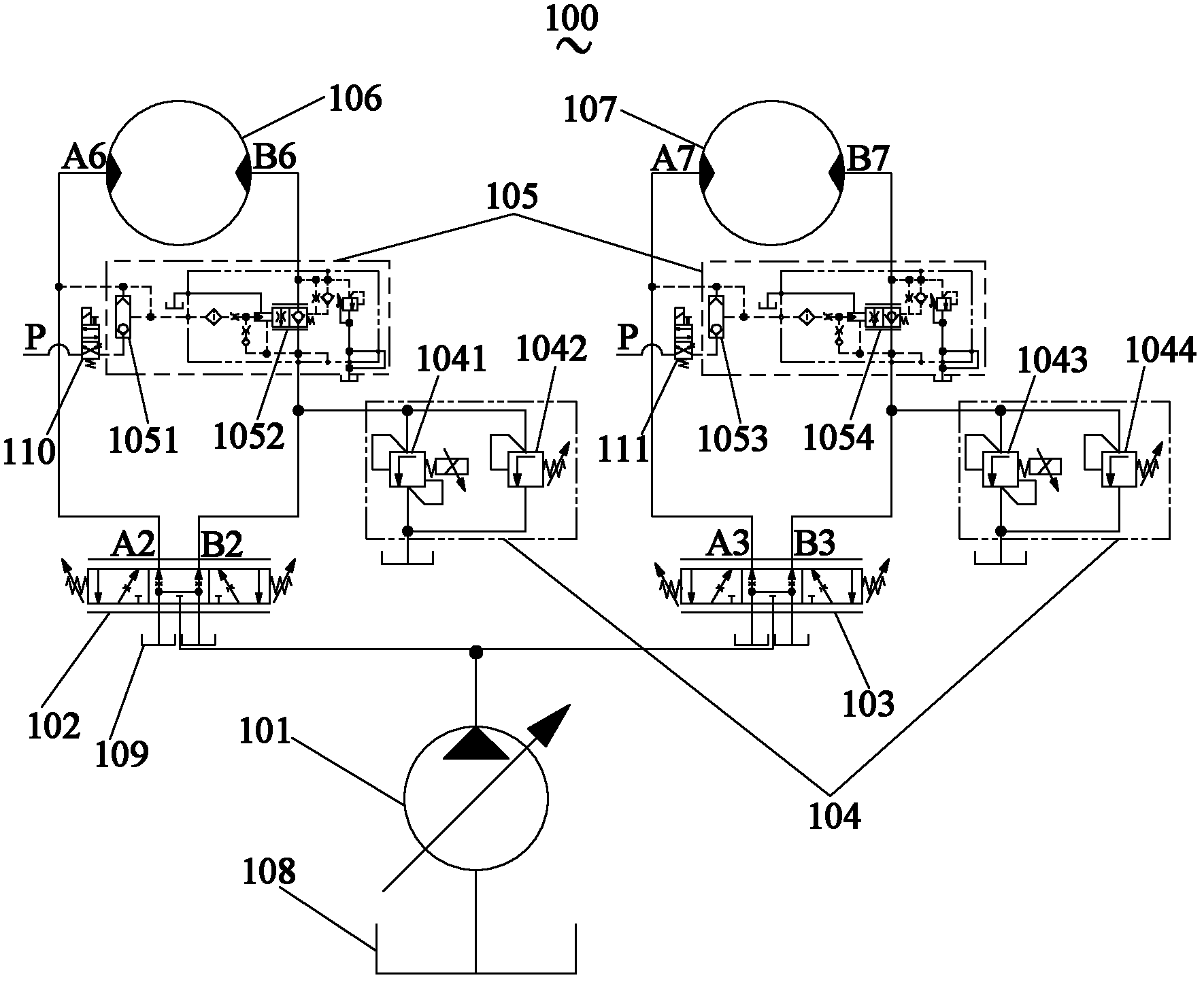
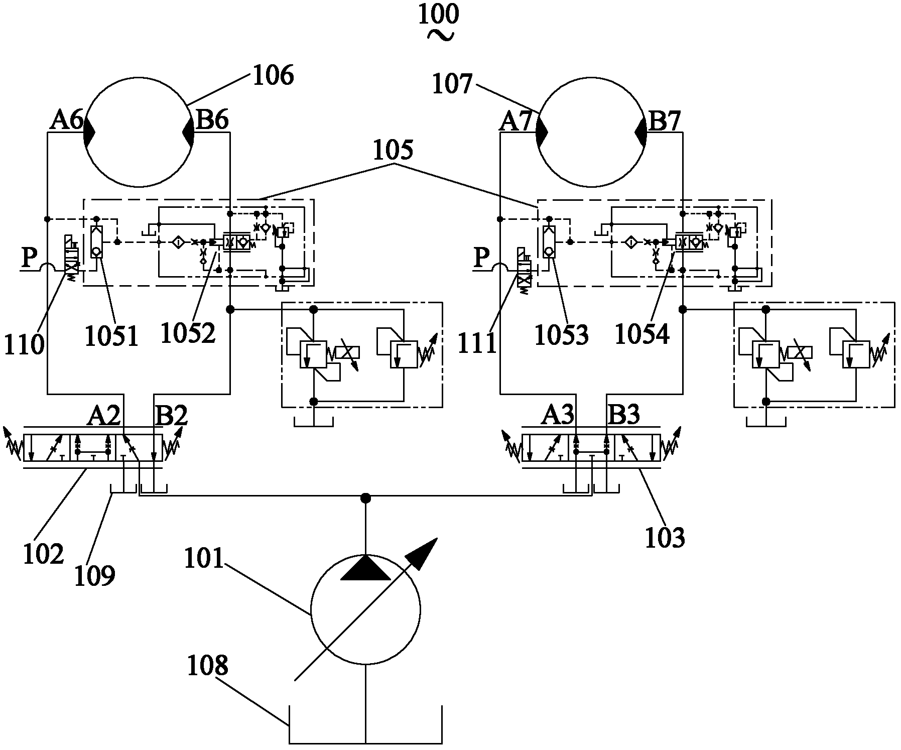
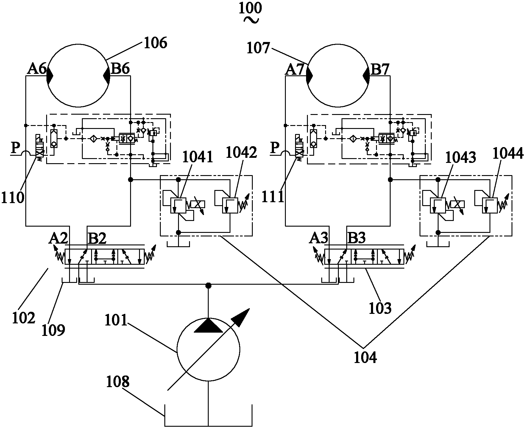
[0025] See figure 1 , figure 1 It is a schematic diagram of the hydraulic principle of the hydraulic control system of the first embodiment of the present invention.

[0026] The hydraulic control system 100 includes an oil pump 101, a first reversing valve 102, a second reversing valve 103, a first motor 106, a second motor 107 and a control unit (not shown), the control unit can be located in any part of the hydraulic control system Position, which has a variety of control methods, such as electrical signal control, hydraulic signal control, manual control or a combination thereof. In this embodiment, the hydraulic control system 100 preferably includes both a rope receiving unit 104 and a rope releasing unit 105, so that the hydraulic control system 100 can be used as both a rope receiving hydraulic control system and a rope releasing hydraulic c...


PUM


Abstract

The invention discloses a hydraulic rope unreeling control system and a hydraulic rope reeling control system, which respectively comprise an oil pump, a first reversing valve, a second reversing valve, a first motor, a second motor and a control unit. The oil pumps are connected with system oil sources, the first reversing valves and the second reversing valves, and the first reversing valves and the second reversing valves are connected with the first motors and the second motors. The hydraulic rope unreeling control system further comprises a rope unreeling unit which comprises a first balance valve unit and a second balance valve unit. The hydraulic rope reeling control system further comprises a rope reeling unit which comprises a first pressure regulating valve unit and a second pressure regulating valve unit. The control units are used for controlling the first reversing valves, the second reversing valves, the rope unreeling unit and / or rope reeling unit. The invention further discloses a crane. By the aid of coordination of the two motors, rope reeling and unreeling of two winches can realize non-linear synchronization reliably, rope disordering can be avoided, operators can debug conveniently and cost is saved.

Description

technical field [0001] The invention relates to the field of cranes, in particular to a rope-releasing hydraulic control system, a rope-retracting hydraulic control system and a crane. Background technique [0002] The current cranes require multiple hoists to act in concert. When these hoists take in or release the rope, because the length of the rope, the size of the pulley, and the position of the wire rope on the jib are different, the actions between the multiple hoists are nonlinear, so It is difficult to control multiple winches to achieve synchronization. [0003] If the winding and unwinding ropes of multiple hoists are not synchronized, the following problems will be caused: the hoist with a relatively slow unwinding speed will bear a large load, and the steel wire rope will be in an over-tensioned state, which will have a negative impact on the service life of the steel wire rope and the service life of the hydraulic motor. Negative impact: The winch with a relat...

Claims


Application Information

Patent Timeline
IPC IPC(8): B66D1/44
CPCB66D1/44B66C13/20
Inventor 詹纯新刘权高一平黎伟福涂凌志宋春阳张源李葳袁知华
Owner ZOOMLION HEAVY IND CO LTD
Why Eureka
Try Eureka