
Roller coal mining machine

A coal shearer and drum technology, applied in the field of drum shearer, can solve the problems of low cutting engine power, poor pressurization performance, and low driving winch power

Inactive Publication Date: 2012-07-11
MARCO SYSTEMANALYSE UND ENTWICKLUNG GMBH
View PDF6 Cites 3 Cited by
  • Summary
  • Abstract
  • Description
  • Claims
  • Application Information

AI Technical Summary

Problems solved by technology

Here, the following are particularly disadvantageous in terms of already usable machines: the lower power of the cutting engine, the lower power of the drive winch, the lower stability of the machine (climbing or jumping), the poorer pressurization ( The conveying tunnel for coal in the drum has a smaller cross-section, the coal flow is blocked by the arms), a smaller tunnel is formed under the machine due to the machine being positioned as a bridge on the conveyor belt, the speed at which the baffles can follow the drum is lower, The drum operator achieves less speed while controlling the machine

Method used


Image

  • Roller coal mining machine
  • Roller coal mining machine
  • Roller coal mining machine

Examples


Embodiment Construction

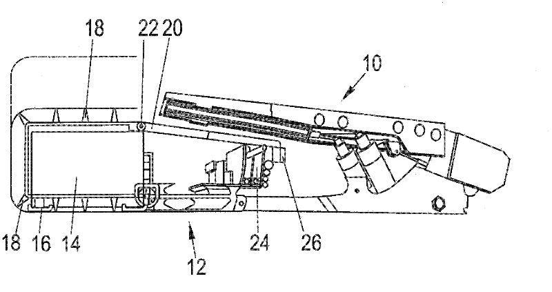
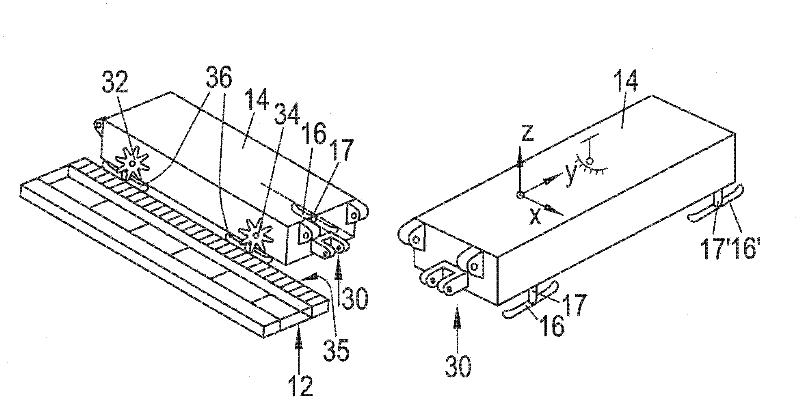
[0018] exist figure 1 shows schematically a side view of a working surface with a shed combination 10 on which a conveyor belt 12 is articulated in a known manner. The machine body of the shearer is marked with reference number 14, which is schematically represented by a box in the figure. The rolling shearer moves on the conveyor belt 12 using two outriggers. The roller shearer is guided on the coal mining road wall by two slides 16 which are adjustable in height and held in their vertical height position by a control. The chisels of the drum are indicated with reference numeral 18 .

[0019] The power supply to the machine body 14 takes place via a cable bridge 20 which is fastened via hinges 22 to the machine frame of the shearer. On the side of the working surface of the conveyor belt 12 , the cable bridge 20 is supported by sliding guides on the frame of the cable tunnel 24 . The control device 26 is connected with the cable bridge 20, and the roller shearer is operat...


PUM


Abstract

The invention relates to a roller coal mining machine used for mining the underground coal mine, comprising a machine body moving along a conveyer belt and at least two cutting rollers respectively mounted on one support arm, wherein the machine body is arranged on at least four elements, two driven elements operate on roller teeth and the other two elements are arranged on a slider plate supported on a lower disk.

Description

technical field [0001] The invention relates to a drum shearer. Background technique [0002] Drum shearers are the most frequently used mining machines in the mining field. The structure and production of such machines have been optimized for a long time. But it has been shown that the structures commonly used today are limited to rock formation thicknesses below only 1.4m. The power of the engine increases with the volume, or decreases with the smaller volume. This fact significantly limits the power provided by the engine for a smaller structural height when the structure of the drum shearer is the same. In addition to the power provided, especially the boost performance is an important criterion for the construction of an efficient machine. [0003] The overall power of the machine is limited by the geometry. Here, the following are particularly disadvantageous in terms of already usable machines: the lower power of the cutting engine, the lower power of the drive wi...

Claims


Application Information

Patent Timeline
Patent Type & Authority Applications(China)
IPC IPC(8): E21C35/06E21C29/00
CPCE21C29/00E21C29/14E21C27/02
Inventor 马丁·路透
Owner MARCO SYSTEMANALYSE UND ENTWICKLUNG GMBH
Learn More