Clamping band

A technology of clamps and hoop parts, which is applied in the directions of clothing, elastic couplings, connecting components, etc., can solve the problems of increasing the production cost of clamps and so on.

Active Publication Date: 2012-07-11
MIHAMA
View PDF7 Cites 6 Cited by
  • Summary
  • Abstract
  • Description
  • Claims
  • Application Information

AI Technical Summary

Problems solved by technology

However, the production cost of the clamp must be further increased

Method used


Image

  • Clamping band
  • Clamping band
  • Clamping band

Examples


Embodiment Construction

[0032] Preferred embodiments of the present invention will now be described in detail with reference to the accompanying drawings.

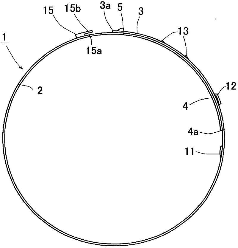
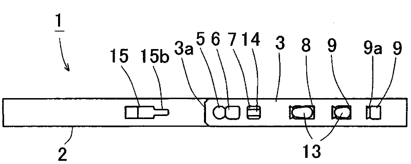
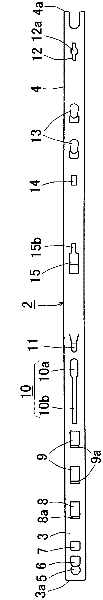
[0033] First, refer to Figure 1A to Figure 2B The structure of the clip related to the present invention will be described.

[0034] The clamp 1 has a clamp part 2 comprising an outer clamp part 3 and an inner clamp part 4 . The outer hoop portion 3 and the inner hoop portion 4 can overlap each other so that the hoop portion 2 can be formed into a ring shape. The hoop portion 2 is a metal strip composed of, for example, stainless steel (for example, SUS301, SUS304, SUS430) and formed in an arc shape. The outer cuff portion 3 and the inner cuff portion 4 overlap each other and are temporarily engaged with each other. In this temporarily clamped state, the outer hoop part 3 and the inner hoop part 4 are moved close to each other by a tool, so that the inner diameter of the annular hoop part 2 is reduced for a clamping action.

[0035] The foll...


PUM


Abstract

The clamping band has a simple structure and is capable of preventing crush of an engaging claw and buckle of an inner band part, which are caused when an outer band part and the inner band part are moved close to each other to reduce an inner diameter of a band section. In the clamping band, an overriding guide is formed between the engaging claw and a second tool-catching claw of the inner band part. The overriding guide is outwardly projected to radially outwardly guide an outer end of the outer band part when the engaging claw is moved to an engage hole from a temporary engage hole.

Description

technical field [0001] The present invention relates to a clamping band for fixing, for example, a boot covering a vehicle constant velocity universal joint. Background technique [0002] Various types of clips for fixing, for example, a boot covering a vehicle constant velocity universal joint have been used. An example of the band has an annular metal band section of which an outer band part and an inner band part overlap each other, and engaging claws are engaged with engaging holes so that the band section The inner diameter is reduced, and a member to be clamped, for example, a boot covering a vehicle constant velocity universal joint can be clamped and fixed. [0003] For example, the outer hoop portion includes a first tool engaging claw, a slit extending from the first tool engaging claw, and a plurality of engaging holes. A first tool engaging claw, a slit, and a plurality of engaging holes are sequentially formed. The inner hoop portion overlapping the outer hoo...

Claims


Application Information

Patent Timeline
Patent Type & Authority Applications(China)
IPC IPC(8): F16B2/20F16D3/84
CPCF16B2/08F16D3/84F16D3/00Y10T24/1478Y10T24/1457Y10T24/1482Y10T24/1412Y10T24/1484
Inventor 伊藤尚纪
Owner MIHAMA
Why Eureka
Try Eureka