Electromagnetic brake

A technology of electromagnetic brakes and brakes, applied in the direction of brake types, axial brakes, gear transmission mechanisms, etc., can solve the problems of small braking torque, reduce equipment cost, disadvantages, etc., achieve large braking torque, simple structure, reduce The effect of equipment cost

Inactive Publication Date: 2012-07-11
XUZHOU KAILAN INFORMATION TECH
View PDF0 Cites 4 Cited by
  • Summary
  • Abstract
  • Description
  • Claims
  • Application Information

AI Technical Summary

Problems solved by technology

[0002] At present, although the mechanism principles of electromagnetic brakes are different, they generally have the defects of complex mechanism and small braking torque, which is not conducive to reducing the cost of equipment and being used in occasions requiring large braking torque.

Method used


Image

  • Electromagnetic brake
  • Electromagnetic brake

Examples


Embodiment Construction

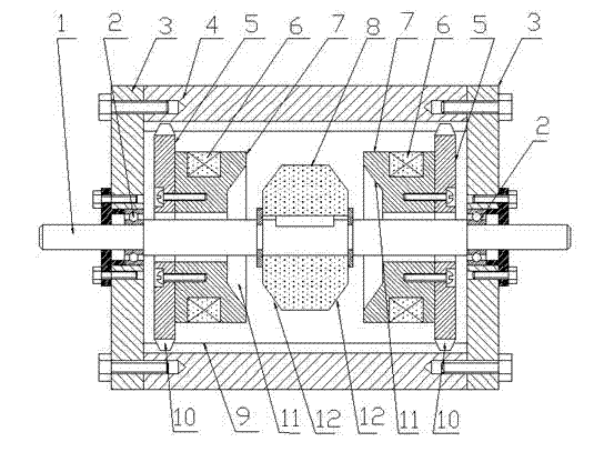
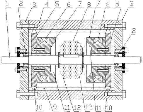
[0009] An electromagnetic brake, which includes: brake shaft 1, bearing 2, end cover 3, brake body 3, guide ring 4, electromagnetic coil 5, electromagnet core 6, brake wheel 7, the middle of the brake body 4 has a straight The round hole is formed with internal spline teeth 9 on the surface of the inner round hole of the brake body 4, and an end cover 3 is installed and fixed at the mouths at both ends of the brake body 4, and the brake shaft passes through two bearings 2 and the ends on the left and right sides. The cover 3 is installed and fixed, and the brake wheel 8 is installed and fixed in the middle of the brake shaft 1. A guide ring 5 is respectively arranged in the inner hole of the brake body 4 on both sides of the brake wheel 8, and the guide ring 5 is annular. The outer spline teeth 10 are formed on the outer circle of the guide ring 5, and the guide ring 5 is installed together by cooperating with the inner spline teeth 9 in the inner hole of the brake body 4 thr...


PUM


Abstract

An electromagnetic brake is characterized in that two end caps are respectively mounted at two end ports of a brake body, a brake shaft is fixedly mounted with the two end caps on the left and the right through bearings, a brake wheel is mounted in the middle of the brake shaft, two guide rings are respectively arranged in inner holes, on two sides of the brake wheel, of the brake body, an electromagnetic iron core is fixedly mounted on the inner side of each guide ring, and electromagnetic coils with the same parameters are respectively embedded in the two corresponding electromagnetic iron cores. The two electromagnetic coils mounted oppositely attract or repel mutually so that inner cones and outer cones among the electromagnetic iron cores and the brake wheel can be matched with each other or separated from each other to realize braking or releasing. The electromagnetic brake has the advantages of simple structure, safety and reliability and high braking torque, can meet requirements of sites needing higher braking torque, and accordingly can reduce equipment cost.

Description

technical field [0001] The invention relates to a brake, in particular to an electromagnetic brake, and belongs to the technical field of electromagnetic brakes. Background technique [0002] At present, although the mechanism principles of electromagnetic brakes are different, they generally have the defects of complex mechanism and small braking torque. Therefore, it is not conducive to reducing the cost of equipment and being used in occasions requiring large braking torque. Contents of the invention [0003] The purpose of the present invention is to provide an electromagnetic brake with simple structure and high braking torque, which can meet the needs of some places requiring high braking torque and reduce equipment cost. [0004] The technical solution adopted by the present invention to achieve the above object is: an electromagnetic brake, which includes: a brake shaft, a bearing, an end cover, a brake body, a guide ring, an electromagnetic coil, an electromagneti...

Claims


Application Information

Patent Timeline
Patent Type & Authority Applications(China)
IPC IPC(8): F16D55/225F16D121/20
Inventor 张朝英
Owner XUZHOU KAILAN INFORMATION TECH
Why Eureka
Try Eureka