
Electromagnetic caliper type brake

A caliper brake, electromagnetic technology, applied in the direction of brake type, brake components, brake actuators, etc., can solve problems such as increased cost, increased assembly process, complex coordination, etc., to extend service life, improve safety, eliminate The effect of small gaps

Inactive Publication Date: 2012-07-11
SUZHOU TORIN DRIVE EQUIP
View PDF7 Cites 5 Cited by
  • Summary
  • Abstract
  • Description
  • Claims
  • Application Information

AI Technical Summary

Problems solved by technology

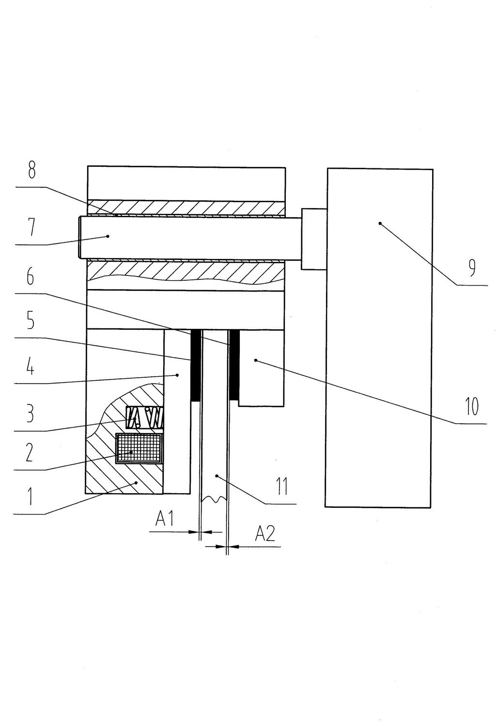
However, the structure of the disc brake to evenly divide the distance between the brake disc and the friction plates on both sides uses non-standard parts such as fixed rods, fixed plates, levers and spring clips, which increases the cost, complicates the coordination, and increases the assembly process.

Method used


Image

  • Electromagnetic caliper type brake
  • Electromagnetic caliper type brake
  • Electromagnetic caliper type brake

Examples


Embodiment 1

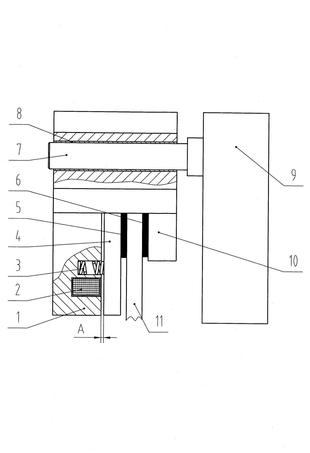
[0028] see Figure 7 , Figure 9 , the electromagnetic caliper brake disclosed in the figure is used to clamp the brake disc 11 of the traction machine, so it is used as a normal brake. The brake includes a static disc 1, an electromagnetic coil 2, a brake spring 3, a moving disc 4, a left , right friction plate 5,6, guide rod 7, mounting seat 9, brake caliper 10, lining ring 15, steel ball cage 16, small bushing 17, the shape of described static disc 1, moving disc 4 can be Circular, rectangular or other irregular shapes, preferably disc-shaped in this embodiment, an electromagnetic coil 2 and a brake spring 3 are arranged in the static disc 1, and the brake caliper 10 and the static disc 1 are fixed by screw connection , the left friction plate 5 is pasted on the inside of the moving disc 4, the right friction plate 6 is pasted on the inside of the brake caliper 10, the left and right friction plates 5, 6 are used to clamp the brake disc 11, and the brake caliper 10 is ...

Embodiment 2

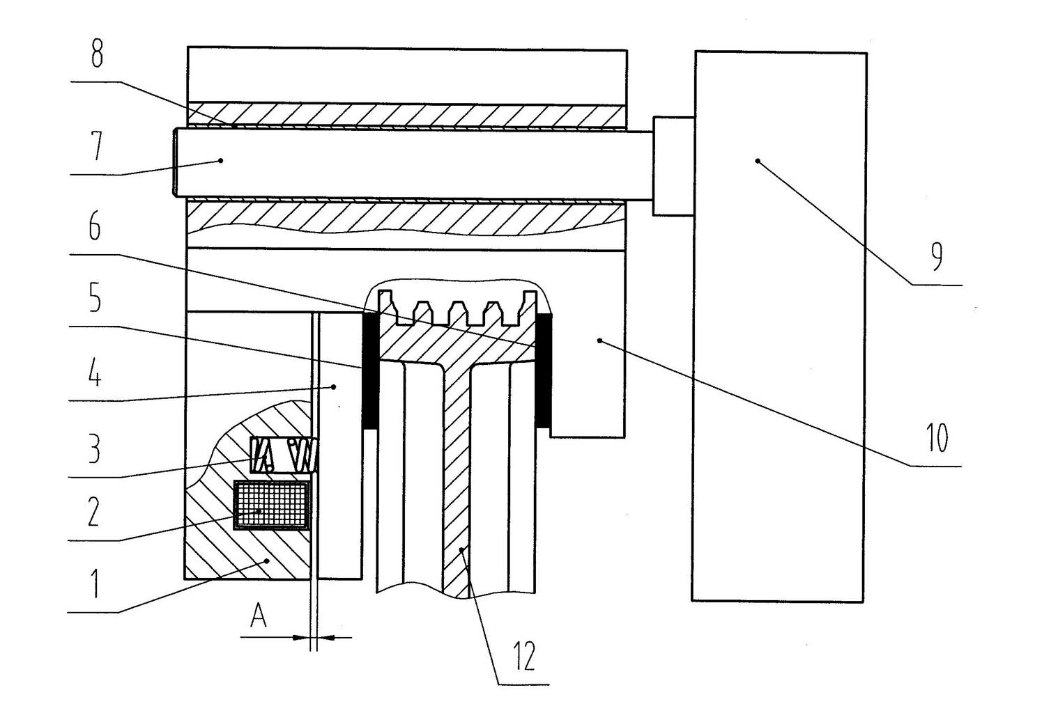
[0030] see Figure 8 The difference between this embodiment and Embodiment 1 is that the electromagnetic caliper brakes are directly clamped on both sides of the traction sheave 12 as emergency brakes, and the rest are the same as the description of Embodiment 1.


PUM


Abstract

An electromagnetic caliper type brake belongs to the technical field of brakes and comprises a movable disc, a static disc, an electromagnetic coil, a braking spring, a brake caliper, a left friction plate, a right friction plate, a mounting seat and a guide rod. The electromagnetic coil and the braking spring are respectively disposed in the static disc, the braking caliper is fixed with the static disc, the left friction plate is attached onto the inner side of the movable disc, the right friction plate is attached on the inner side of the brake caliper, the mounting seat is used for being fixed with a traction machine, and the guide rod is penetratingly arranged in a mounting hole of the brake caliper and fixed with the mounting seat. The electromagnetic caliper type brake is characterized in that a lining ring is disposed in the mounting hole of the braking caliper, a steel ball retainer is sleeved on the guide rod, a steel ball on the steel ball retainer is respectively in rolling fit with an inner peripheral surface of the lining ring and an outer peripheral surface of the guide rod, so that the braking caliper can move in parallel relative to the guide rod, and the guide rod is provided with an anti-slipping mechanism which is used for preventing the steel ball retainer from slipping off from the guide rod. The electromagnetic caliper type brake has the advantages that automatic adjustment and equidistant division of clearances under optional states can be realized, safety of a braking system is improved, and the electromagnetic caliper type brake is convenient in maintenance.

Description

technical field [0001] The invention belongs to the technical field of brakes, in particular to an electromagnetic caliper brake installed on an elevator traction machine for emergency braking or normal braking, which is an improvement on the structure of the existing electromagnetic caliper brake. Background technique [0002] In the prior art, the electromagnetic caliper brake applied to the elevator traction machine for normal braking or emergency braking has a structure of figure 1 , figure 2 As disclosed, it includes a static disc 1, an electromagnetic coil 2, a brake spring 3, a moving disc 4, a left friction plate 5, a right friction plate 6, a guide rod 7, a bushing 8, a mounting seat 9 and a brake caliper 10. The disc 1 is provided with an electromagnetic coil 2 and a brake spring 3. The brake caliper 10 and the static disc 1 are connected and fixed by screws, and the static disc 1 and the movable disc 4 are connected in series by a bolt assembly, and the two are ...

Claims


Application Information

Patent Timeline
Patent Type & Authority Applications(China)
IPC IPC(8): F16D65/092F16D65/14B66D5/14B66D5/30F16D121/20
Inventor 曹建文曹宇钟韬
Owner SUZHOU TORIN DRIVE EQUIP
Learn More