Speed shifting tool and speed shifting control method thereof

A technology of gear shifting tools and control methods, which is applied in the direction of manufacturing tools, transmission device control, gear transmission devices, etc., can solve the problems of complex mechanical structure of gear transmission mechanism and the inability to truly realize the industrialization of automatic gear shifting, and achieve the goal of shortening the pause Time, prolong service life, avoid the effect of grinding problems

Active Publication Date: 2012-07-11
POSITEC POWER TOOLS (SUZHOU) CO LTD
View PDF9 Cites 4 Cited by
  • Summary
  • Abstract
  • Description
  • Claims
  • Application Information

AI Technical Summary

Problems solved by technology

The above-mentioned automatic transmission mechanisms realize automatic gear shifting based on the change of the positional relationship between the mechanical structures corresponding to the change of the output torque. This mechanical transmission mechanism not only makes the internal mechanical structure of the gear transmission mechanism more complicated, but also due to the It is also rotating while moving axially, and the housing is relatively fixed, so when the speed change mechanism is shifting, the teeth of the rotating ring gear and the teeth of the anti-rotation device on the housing will collide with each other and it is difficult to meshing, so the purpose of automatic gear shifting and industrial implementation cannot be really realized

Method used


Image

  • Speed shifting tool and speed shifting control method thereof
  • Speed shifting tool and speed shifting control method thereof
  • Speed shifting tool and speed shifting control method thereof

Examples


Embodiment Construction

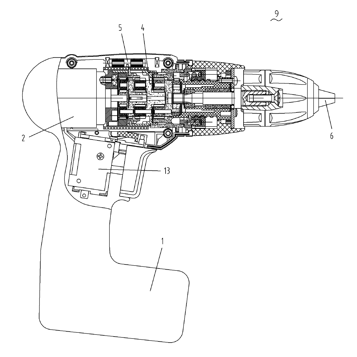
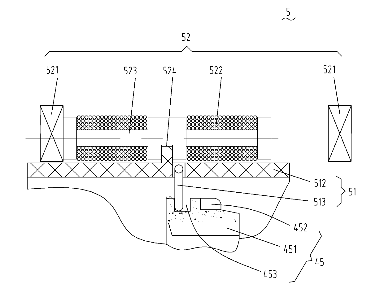
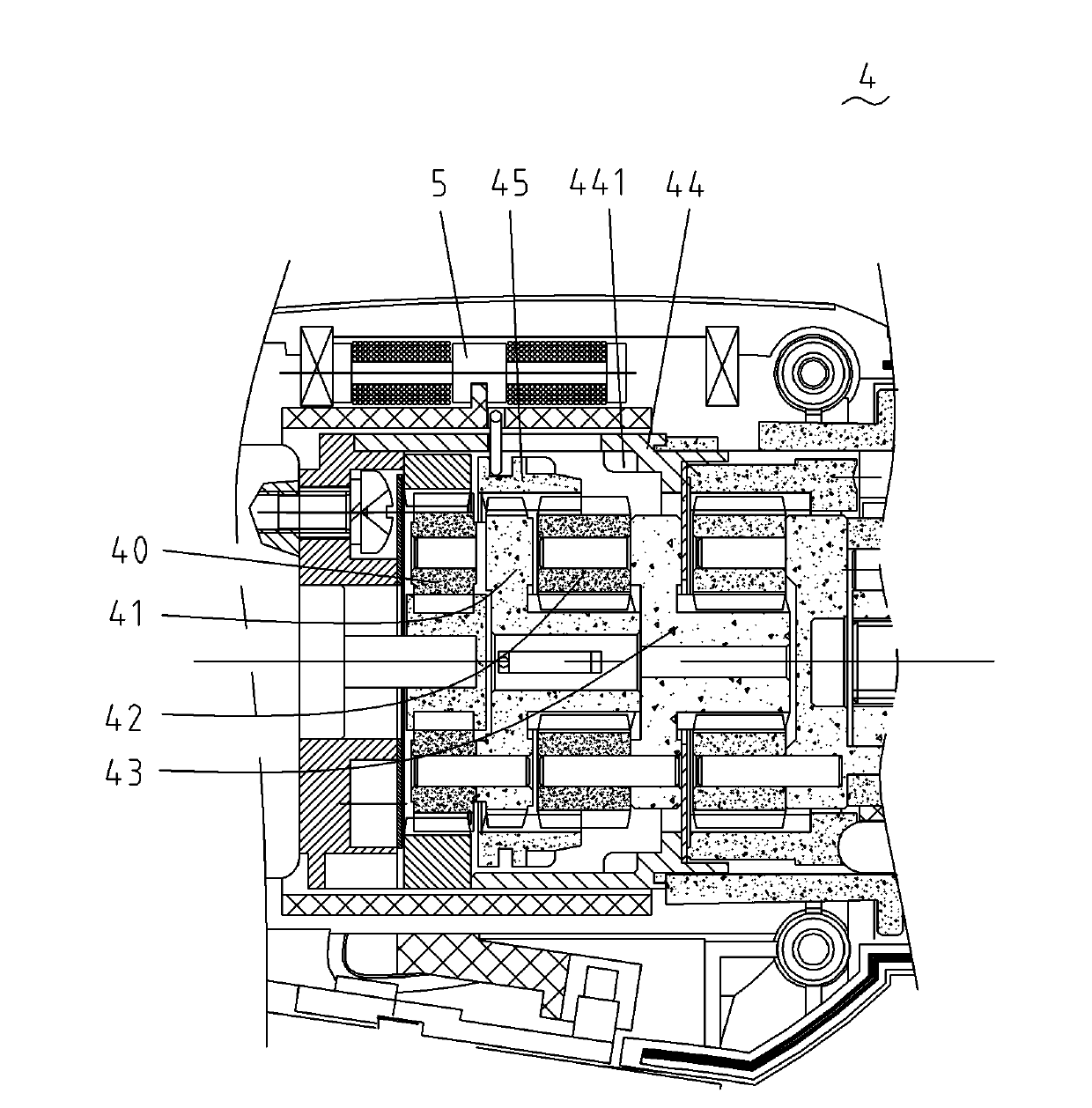
[0050] refer to Figure 1 to Figure 3b As shown, it is a structural schematic diagram of the first embodiment of the driving device of the variable speed tool control system of the present invention. A variable speed tool 9 includes a motor 2 , a motor power supply 1 , a main switch 13 for starting / stopping the motor, an output shaft 6 and a gear transmission mechanism 4 . The gear transmission mechanism 4 includes a first planetary gear set composed of a first planetary gear 40 and a first planetary carrier 41, a second planetary gear set composed of a second planetary gear 42 and a second planetary carrier 43, and is fixedly arranged on the tool housing. The anti-rotation device 44 on the body and the moving part 45 that can move axially. The driving device 5 is arranged on the gear transmission mechanism 4, and comprises a driving member 52 and a transmission member 51. The driving member of the present embodiment adopts an electromagnet device, including two permanent mag...


PUM


Abstract

The invention discloses a speed shifting tool which comprises a case, a motor, an output shaft, a gear transmission mechanism and a control system, wherein the motor is arranged in the case and outputs rotary power; the gear transmission mechanism is arranged between the motor and the output shaft so as to transmit rotary output to the output shaft and comprises at least one gear train and a moving piece, the moving piece can move between the fist position and the second position, and the moving piece and the gear train are matched in different ways in the first position and the second position so that the gear transmission mechanism outputs the speed of the motor in different reduction ratios; and the control system comprises a driving device matched with the moving piece, the driving device is used for driving the moving piece to move between the first position and the second position, and the control system also comprises an electronic switch in parallel to the motor. When the reduction ratio of the gear transmission mechanism requires changing, the control system cuts off the current of the motor, connects the electronic switch and controls the driving device to drive the moving piece to move between the first position and the second position.

Description

technical field [0001] The invention relates to a variable speed tool, in particular to a tool driven by a motor with a variable speed transmission mechanism that can output different rotational speeds, such as electric drills, screwdrivers and hammer drills. The invention also relates to a speed change control method of this type of speed change tool. Background technique [0002] A variable speed tool, such as an electric drill, screwdriver and hammer drill, etc., has a variable speed transmission mechanism that can output different speeds to adapt to different load torques. The speed change transmission mechanism of the speed change tool usually includes a gear transmission mechanism connecting the motor and the output shaft and a control system. The control system changes the transmission ratio by changing the meshing relationship with the gear transmission mechanism, so that the output shaft outputs different speeds. In the prior art, such as the automatic transmission...

Claims


Application Information

Patent Timeline
Patent Type & Authority Applications(China)
IPC IPC(8): F16H3/08F16H59/04F16H61/00B25F5/00
Inventor 刘芳世钟红风
Owner POSITEC POWER TOOLS (SUZHOU) CO LTD
Why Eureka
Try Eureka