Dynamic constant-pressure constant-flow regulating valve

A technology of constant pressure and constant flow, regulating valve, applied in the field of regulating valve, can solve problems such as automatic adjustment of water output by faucet, reduction of water demand, adjustment of faucet, etc.

Inactive Publication Date: 2012-07-11
LUSHAN COLLEGE OF GUANGXI UNIV OF SCI & TECH
View PDF7 Cites 12 Cited by
  • Summary
  • Abstract
  • Description
  • Claims
  • Application Information

AI Technical Summary

Problems solved by technology

[0002] For the urban water supply system, the daily water supply fluctuates greatly with the changes of each time period. Generally, the water demand in the morning, noon and evening peak hours is relatively large, and the water demand in other periods is greatly reduced. Today The faucets commonly used by people generally do not have a device to automatically adjust the water output according to the water pressure of the pipe network. When the faucet is turned to the same position, the water output is large when the pipe network pressure is high, and the water output is small when the pipe network pressure is low. When the water consumption does not need to be so large, the current practice is to artificially adjust the opening of the faucet to adjust the water output. In many public places, people generally do not adjust the opening of the faucet according to their own water demand. would cause a lot of waste

Method used


Image

  • Dynamic constant-pressure constant-flow regulating valve
  • Dynamic constant-pressure constant-flow regulating valve
  • Dynamic constant-pressure constant-flow regulating valve

Examples


Embodiment 1

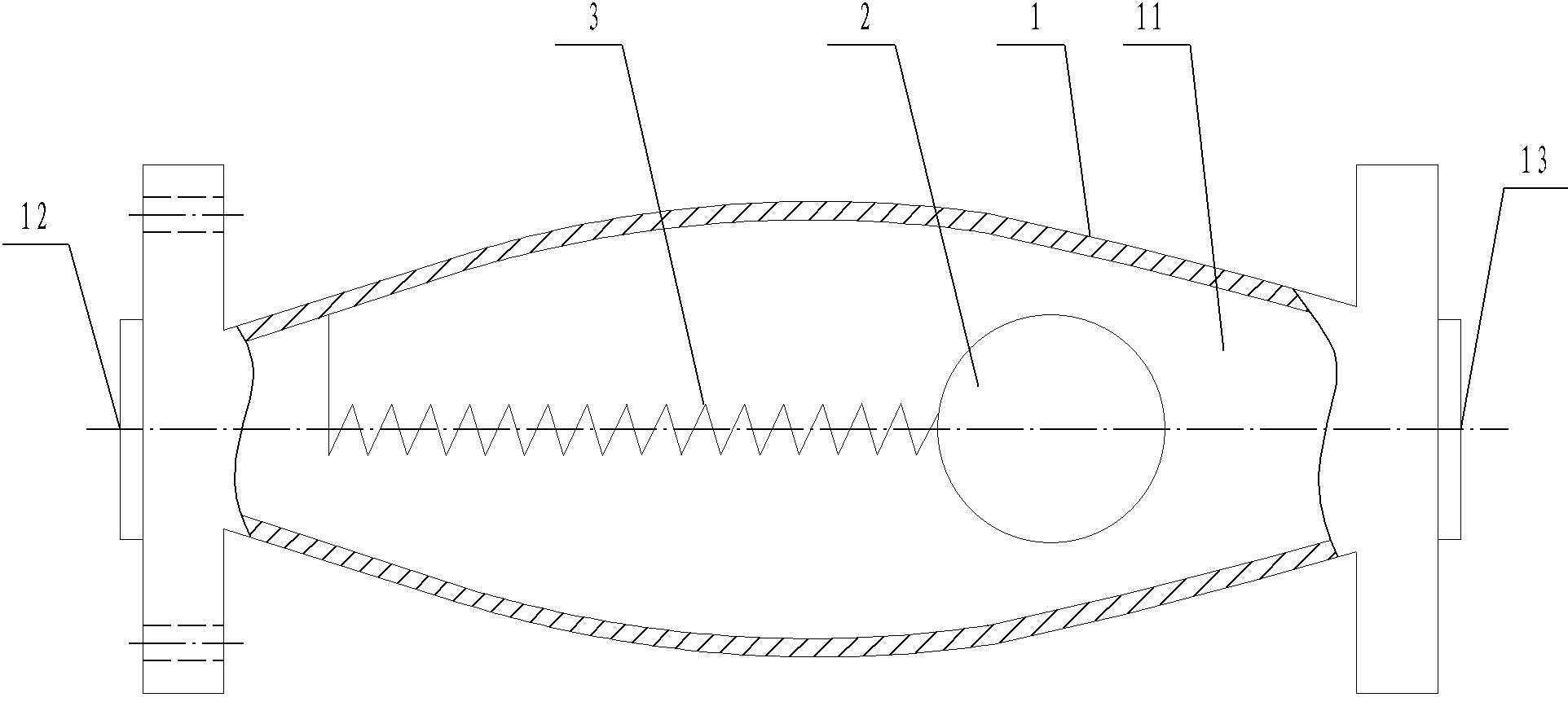
[0028] A dynamic constant pressure and constant flow regulating valve (see figure 1 ), including a valve body 1, a cavity 11 is provided in the valve body 1, and a water inlet 12 and a water outlet 13 are respectively opened at both ends of the valve body 1. The dynamic constant pressure and constant flow regulating valve also includes a throttling ball 2 and Spring 3, one end of the spring 3 is fixed on the valve body 1 near the water inlet 12, the other end is fixedly connected with the throttling ball 2, the throttling ball 2 is located near the water outlet 13, the cross-sectional area of ​​the cavity 11 in the valve body It gradually decreases from the middle to both ends, forming a drum-shaped cavity, but the diameter of the smallest section is larger than the diameter of the throttling sphere 2. When the water pressure is too high and the water flow becomes larger, the throttling sphere 2 is blocked by the water flow. Push toward the water outlet, because the cavi...

Embodiment 2

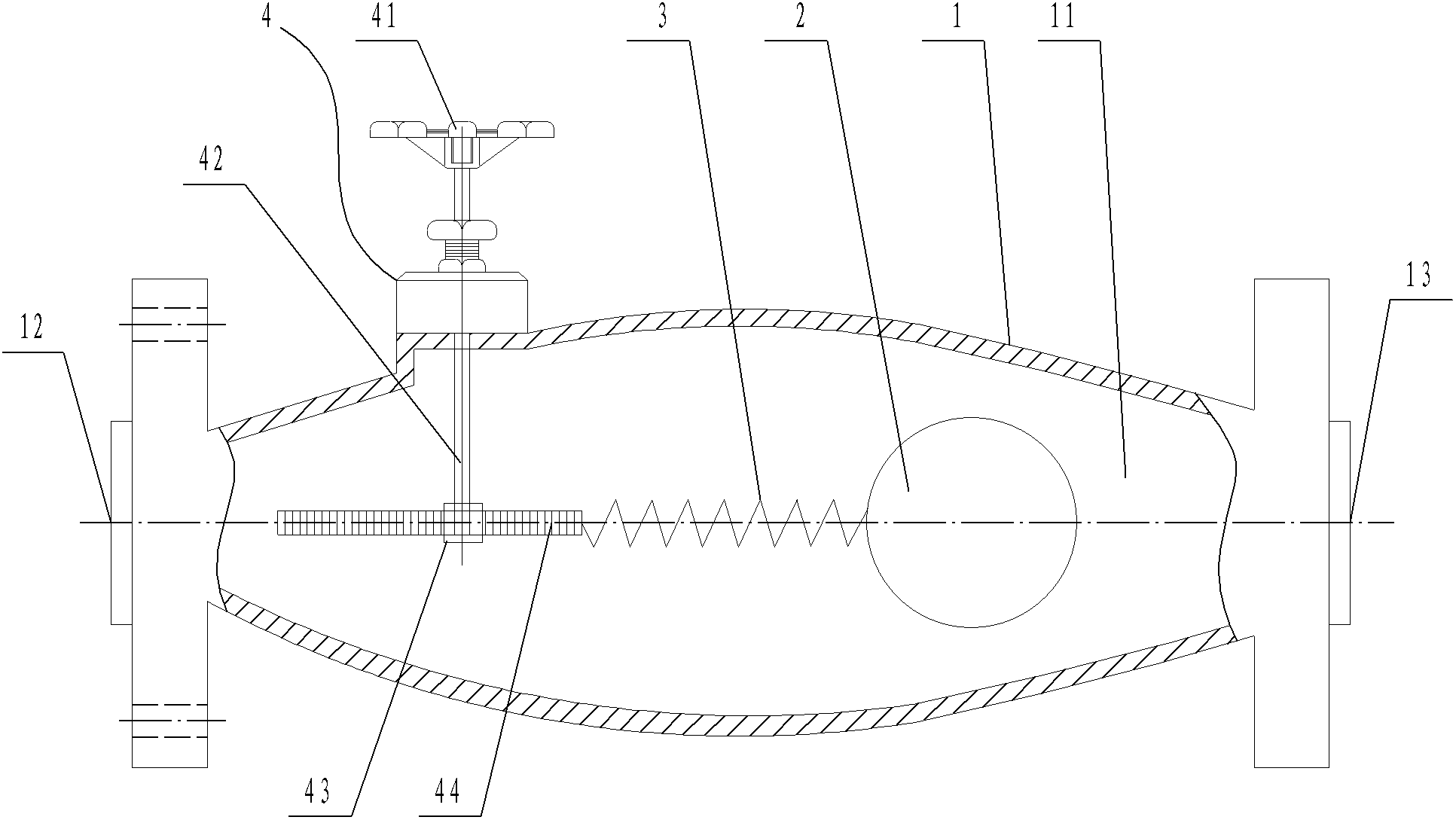
[0030] A dynamic constant pressure and constant flow regulating valve (see figure 2 ), including a valve body 1, a cavity 11 is provided in the valve body 1, and a water inlet 12 and a water outlet 13 are respectively opened at both ends of the valve body 1. The dynamic constant pressure and constant flow regulating valve also includes a throttling ball 2 and Spring 3 and adjusting spring displacement mechanism 4, one end of spring 3 is fixed on the valve body 1 close to the water inlet 12 end, and the other end is fixedly connected with the throttling ball 2, and the cross-sectional area of ​​the cavity 11 in the valve body 1 is determined by the middle It gradually becomes smaller toward both ends to form a drum-shaped cavity, but the diameter at its smallest section is greater than the diameter of the throttle sphere 2; the adjusting spring displacement mechanism 4 includes a hand wheel 41, a valve stem 42, a gear 43, and a tooth Bar 44, wherein the hand wheel 41 is expose...

Embodiment 3

[0031] Embodiment three (best embodiment):

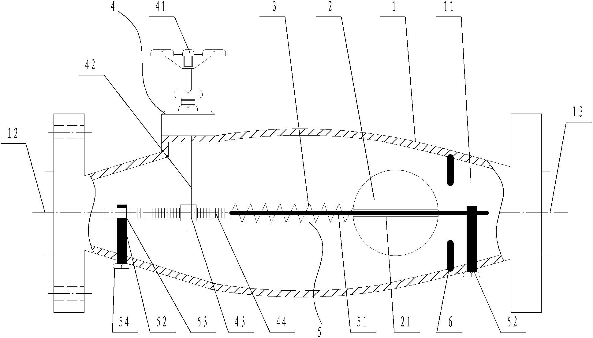
[0032] A dynamic constant pressure and constant flow regulating valve (see image 3 ), including a valve body 1, a cavity 11 is provided in the valve body 1, and a water inlet 12 and a water outlet 13 are respectively opened at both ends of the valve body 1. The dynamic constant pressure and constant flow regulating valve also includes a throttling ball 2 and Spring 3, a through hole 21 is opened in the middle of the throttling sphere 2, one end of the spring 3 is fixed on the valve body 1 close to the water inlet 12, and the other end is fixedly connected with the throttle sphere 2, the inside of the valve body 1 The cross-sectional area of ​​the cavity 11 gradually decreases from the middle to both ends, forming a drum-shaped cavity, but the diameter at the smallest cross-section is greater than the diameter of the throttling sphere 2; the dynamic constant pressure and constant flow regulating valve also includes Adjust the sp...


PUM


Abstract

The invention discloses a dynamic constant-pressure constant-flow regulating valve and relates to a regulating valve. The dynamic constant-pressure constant-flow regulating valve comprises a valve body, a throttling ball body, a spring, a spring displacement regulating mechanism and a cavity supporting structure, wherein a cavity is arranged in the valve body, both ends of the valve body are respectively provided with a water inlet and a water outlet, a through hole is arranged in the middle of the throttling ball body, one end of the spring is fixed on the valve body through the spring displacement regulating mechanism, the other end of the spring is fixedly connected with the throttling ball body, the sectional area of the cavity is gradually reduced from the middle part to two ends, and the diameter of the minimum sectional area is larger than the diameter of the throttling ball body; and the cavity supporting structure comprises a ball body support rod and two fixed rods, wherein one ends of the fixed rods are respectively fixed in the cavity of the valve body, the other ends are provided with sliding support holes, one end of the ball body support rod is arranged in the sliding support hole close to the water outlet, and the other end of the ball body support rod sequentially penetrates through the through hole, the spring and a rack. According to the invention, water outflow can be regulated dynamically according to water pressure so as to achieve the effect of water saving, the service life of a faucet can be prolonged, and the dynamic constant-pressure constant-flow regulating valve has the characteristic of simple structure, and is easy to use and popularize.

Description

technical field [0001] The invention relates to a regulating valve, in particular to a dynamic constant pressure and constant current regulating valve. Background technique [0002] For the urban water supply system, the daily water supply fluctuates greatly with the changes of each time period. Generally, the water demand in the morning, noon and evening peak hours is relatively large, and the water demand in other periods is greatly reduced. Today The faucets commonly used by people generally do not have a device to automatically adjust the water output according to the water pressure of the pipe network. When the faucet is turned to the same position, the water output is large when the pipe network pressure is high, and the water output is small when the pipe network pressure is low. When the water consumption does not need to be so large, the current practice is to artificially adjust the opening of the faucet to adjust the water output. In many public places, people gen...

Claims


Application Information

Patent Timeline
Patent Type & Authority Applications(China)
IPC IPC(8): F16K17/30F16K31/44F16K27/00F16K47/04
Inventor 农胜隆胡义华潘宇倩耿雪霄林发柱
Owner LUSHAN COLLEGE OF GUANGXI UNIV OF SCI & TECH
Why Eureka
Try Eureka