A backlight unit and a liquid crystal display device

A technology of a backlight unit and a light guide plate, which is applied to optical elements, lighting devices, fixed lighting devices, etc., can solve problems such as easy dislocation and dislocation of display areas.

Inactive Publication Date: 2012-07-11
JAPAN DISPLAY INC +1
View PDF7 Cites 3 Cited by
  • Summary
  • Abstract
  • Description
  • Claims
  • Application Information

AI Technical Summary

Problems solved by technology

[0004] However, in the above-mentioned conventional structure, since there is a gap, there is a problem that misalignment easily occurs between the inner frame, the light guide plate, and the outer frame, which causes misalignment of the display area.

Method used


Image

  • A backlight unit and a liquid crystal display device
  • A backlight unit and a liquid crystal display device
  • A backlight unit and a liquid crystal display device

Examples


Embodiment Construction

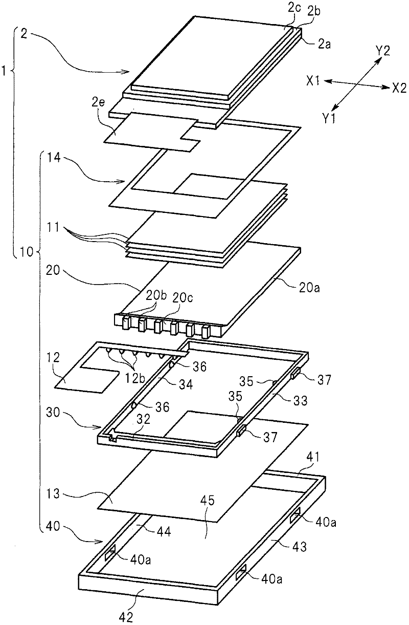
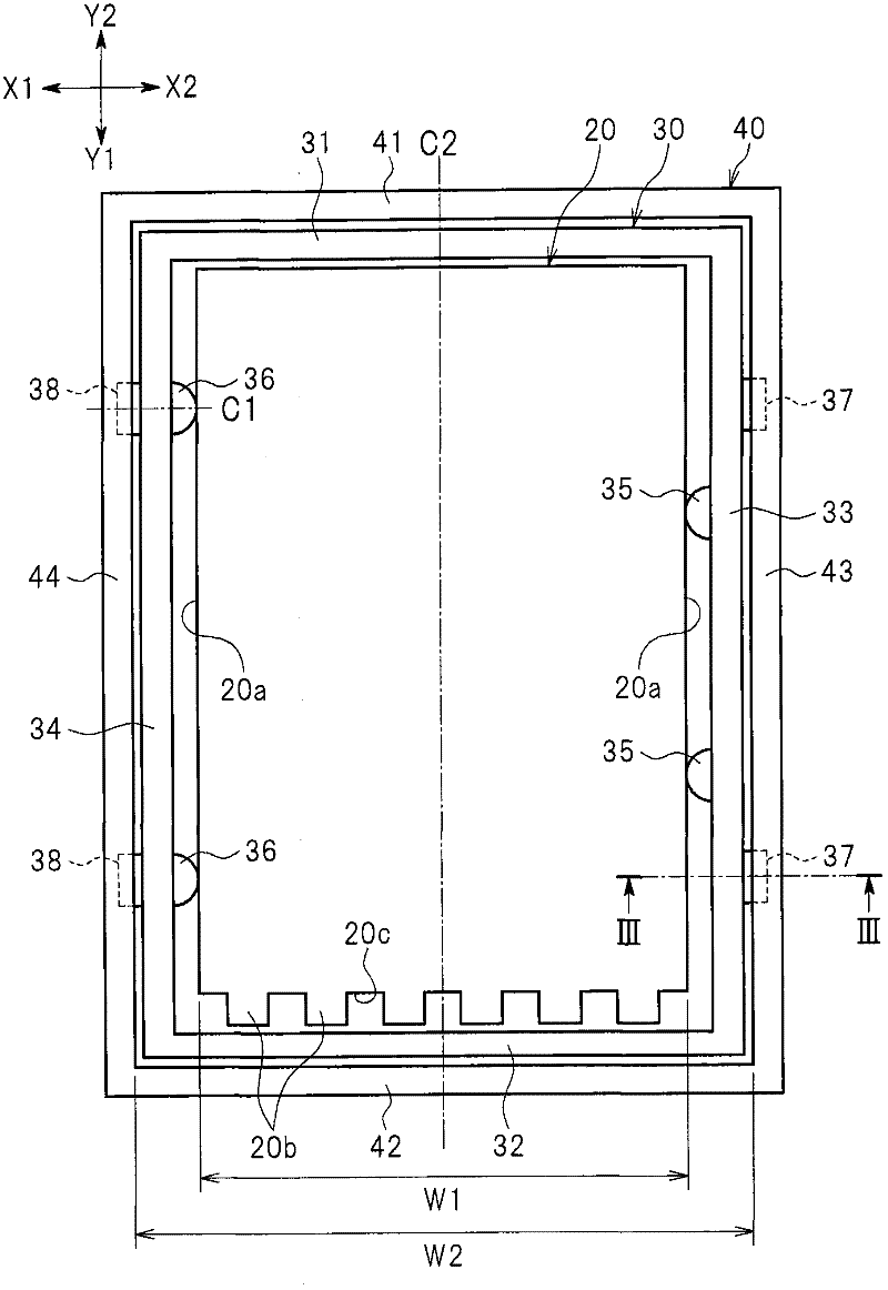
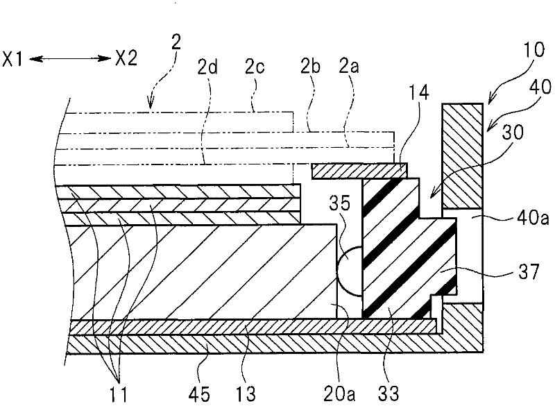
[0050] Hereinafter, an embodiment of the present invention will be described with reference to the drawings. figure 1 It is an exploded perspective view of the liquid crystal display device 1 including the backlight unit 10 according to the embodiment of the present invention. figure 2 It is a plan view of the above-mentioned backlight unit 10 . exist figure 2 In the figure, the light guide plate 20, the inner frame 30, and the outer frame 40 which comprise the backlight unit 10 are shown. image 3 yes figure 2 A cross-sectional view of the backlight unit 10 taken along line III-III. Figure 4 yes figure 2 The enlarged view of the main part of FIG. 2 shows the first inner protrusion 35 and the first outer protrusion 37 formed on the inner frame 30 in this figure. In addition, in the following description, the direction in which the liquid crystal display panel 2 and the backlight unit 10 face each other is defined as the up-down direction. In addition, in figure 1 H...


PUM


Abstract

The present invention provides a backlight unit and a liquid crystal display device. A backlight unit (10) includes a light guide plate (20), an inner frame (30) that surrounds an outer periphery of the light guide plate (20), and an outer frame (40) that surrounds an outer periphery of the inner frame (30). An inner periphery of the inner frame (30) is formed with an inner protrusion (35) that projects toward the outer periphery of the light guide plate (20). The outer periphery of the inner frame (30) is formed with an outer protrusion (37) that projects toward an inner periphery of the outer frame (40). The inner protrusion (35) and the outer protrusion (37) are located on opposite sides of a wall part that is one side part (33) of the inner frame (30), and arranged at a distance from each other in a longitudinal direction of the wall part (33) of the inner frame (30). According to the backlight unit (10), relative positional displacement of members can be suppressed while ensuring the ease of assembling.

Description

technical field [0001] The present invention relates to a backlight unit and a liquid crystal display device, and particularly relates to a technology for reducing relative misalignment of components constituting the backlight unit. Background technique [0002] The backlight unit of a liquid crystal display device disclosed in Japanese Patent Application Laid-Open No. 2009-192769 includes a light guide plate and an inner frame formed of resin that surrounds the outer periphery of the light guide plate. The liquid crystal display panel disposed on the front side of the light guide plate is placed on the inner frame and attached to the inner frame. In addition, the backlight unit disclosed in Japanese Patent Application Laid-Open No. 2009-192769 has an outer frame surrounding an inner frame. The outer frame is formed of metal to increase the strength of the liquid crystal display device. [0003] In such a configuration, gaps are provided between the inner frame and the lig...

Claims


Application Information

Patent Timeline
Patent Type & Authority Applications(China)
IPC IPC(8): F21S8/00F21V8/00F21V17/10G02F1/13357
CPCG02B6/0088G02F1/133308G02B6/002G02F2201/465G02B6/0083G02F2001/133322G02F2001/133317G02F1/133317G02F1/133322G02F1/1333G02F1/1335
Inventor 胁田胜一铃木延幸
Owner JAPAN DISPLAY INC
Why Eureka
Try Eureka