
Thermal imaging device and standard thermal image photographing method

A technology for shooting parts and infrared thermal images, which is applied in image communication, TV, color TV parts, etc.

Inactive Publication Date: 2012-07-11
MISSION INFRARED ELECTRO OPTICS TECH
View PDF4 Cites 87 Cited by
  • Summary
  • Abstract
  • Description
  • Claims
  • Application Information

AI Technical Summary

Problems solved by technology

Patent document application number: 201010201335.8 discloses a thermal imaging device, which has a visible light imaging unit and an infrared imaging unit, which can synthesize and display the captured visible light and infrared thermal images, which can improve the intuitiveness of infrared shooting; Reticle, reticle, etc. are used to assist aiming; however, for the user, even with the above improvements, it does not solve the problem

Method used


Image

  • Thermal imaging device and standard thermal image photographing method
  • Thermal imaging device and standard thermal image photographing method
  • Thermal imaging device and standard thermal image photographing method

Examples


Embodiment 2

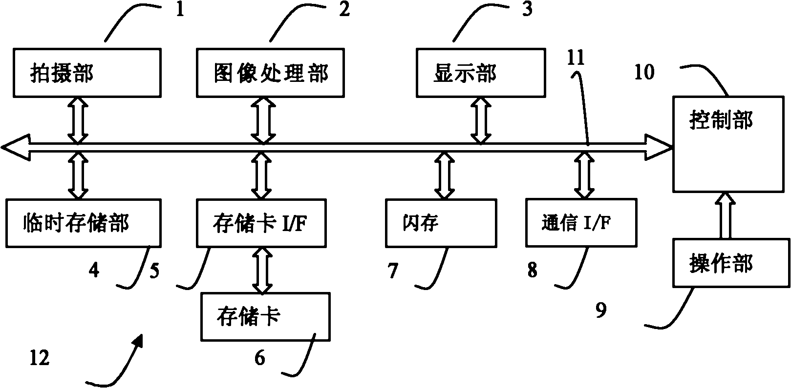
[0100] The difference from embodiment 1 is that this embodiment has the same figure 1 In the shown thermal imaging device 12 with the same structure, the flash memory 7 stores a control program for executing adaptive display of the reference image in the adaptive display area. Figure 14 It is a flowchart showing (adaptive display) reference recording mode processing control. Figure 15 Schematic diagram of the adaptive display effect after "centering the reference image" for the partial contour image. Figure 16 Schematic diagram of the adaptive display effect after "centering the reference range" of the local contour image. Figure 17 It is a schematic diagram of another implementation of the object information and morphological constitution data stored in the storage unit. Figure 18 It is a schematic diagram of another implementation of object information and multiple types of constituent data stored in the storage unit. Figure 19 It is a schematic diagram of the disp...

Embodiment 3

[0122] Embodiment 3, this embodiment is with figure 1 In the thermal imaging device 12 shown with the same structure, different from the first embodiment, the flash memory 7 stores a control program for processing the determined object to obtain morphological composition data. This standard shooting method (reference recording mode for processing, including processing mode and reference recording mode) will be described below. The processing unit (image processing unit 2) is used to perform at least one of cutting, edge extraction, and threshold range extraction on the object to be processed, and the storage unit (temporary storage unit 4, etc.) is used to store the processed object The morphological composition data; the reference composition determination unit (control unit 10 ), which is used to determine the morphological composition data obtained through processing as the composition data related to the reference image to be combined with the infrared thermal image.

[...

Embodiment 4

[0148] This embodiment is with figure 1 In the thermal imaging device 12 with the same structure as shown, the flash memory 7 stores a control program for setting and recording related information of the configuration data. The control unit 10, the operation unit 9, and the display unit 3 are examples of the related information setting unit, which are used to set the setting information of at least one of the analysis area, object information, and indicator information corresponding to the form configuration data. 10 is used as an example of an associated information recording unit for establishing an associated record between form configuration data and setting information.

[0149] For example, in step S303 of Embodiment 3, the morphological composition data obtained after processing is obtained. At this time, the subsequent reference recording mode shooting may not be performed temporarily, and the analysis area, prompt mark, and object corresponding to the morphological c...


PUM


Abstract

The invention discloses a thermal imaging device and a standard thermal image photographing method and relates to the application field of thermal imaging devices and infrared thermal imaging detection. When the thermal imaging device in the prior art is used for taking a photograph, the photographed part, the photographing angle and the photographing distance of a photographed object are required to be selected depending on the subjective experiences of a user, the photographing speed is slow, omission is apt to be caused, the positions, sizes and angles of the thermal images of similar photographed objects in infrared thermal images, the thermal images of the photographed objects are photographed at each time are almost not the same and the subsequent batch processing of the recorded infrared thermal images is difficult. The thermal imaging device and the standard thermal image photographing method provided by the invention have the advantages that the specified position and the specified size and reflected the expect morphological characteristics of the photographed object are presented in the infrared thermal images, the user can obtain visual references which can satisfy the expected thermal image quality and the photographing requirement of the photographed objects, the user is helped to correctly master the imaging morphology and the photographing distance of the thermal images of the photographed objects and the unified and standard thermal images of the photographed objects can be easily recorded and obtained.

Description

technical field [0001] The thermal imaging device and the thermal imaging standard shooting method of the present invention relate to the thermal imaging device and the application field of infrared imaging detection. Background technique [0002] As a well-known technology, a thermal imaging device is widely used for imaging by receiving external infrared energy radiation. In shooting, various subjects have their specific requirements for shooting positions and shooting angles, and present a specific imaging form. Since the birth of infrared thermal image detection technology, users mainly rely on subjective experience to shoot, and it is difficult to grasp the correct imaging form of the subject and the imaging position, size and angle of the thermal image of the subject in the infrared thermal image where it is located. As a result, it is easy to miss key parts during shooting, and there are always differences in the above-mentioned imaging positions, sizes, and angles i...

Claims


Application Information

Patent Timeline
Patent Type & Authority Applications(China)
IPC IPC(8): G01J5/10H04N5/33H04N5/232
Inventor 王浩
Owner MISSION INFRARED ELECTRO OPTICS TECH
Learn More