
Current harmonic detection system and working method

A detection system and current harmonic technology, applied in the field of current harmonic detection system based on improved FBD algorithm and DSP technology, can solve the problems of increasing the amount of calculation, affecting the APF compensation performance, increasing the computing burden of the microprocessor, etc. Solve the effect of large detection delay and improve power supply quality

Inactive Publication Date: 2012-07-11
UNIV OF SHANGHAI FOR SCI & TECH
View PDF2 Cites 10 Cited by
  • Summary
  • Abstract
  • Description
  • Claims
  • Application Information

AI Technical Summary

Problems solved by technology

However, due to the existence of the low-pass filter (LPF) in these detection methods, the detection delay reaches 1 to 2 power cycles, resulting in hysteresis error, which affects the compensation performance of APF
Kuang Naixing of Zhejiang University published a paper "A High-performance Harmonic Detection Digital Low-pass Filter" in the 30th issue of "Power System Automation" in 2006. They designed a new type of low-pass filter to replace the traditional low-pass filter, but increased the complexity of the system
Ding Zujun from Southeast University and others published the paper "Modeling of Hysteresis Error of FBD Algorithm Current Detection" in the 2nd issue of "Journal of Electrotechnical Society" in 2008, which established a hysteresis model of FBD current detection method and introduced a linear transformation compensation algorithm, but the improved method remains A low-pass filter is added, which increases the amount of calculation and increases the computational burden of the microprocessor

Method used


Image

  • Current harmonic detection system and working method
  • Current harmonic detection system and working method
  • Current harmonic detection system and working method

Examples


Embodiment Construction

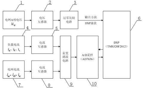
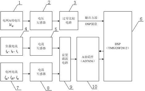
[0016] Such as figure 1 As shown in the schematic diagram of the system, the present invention includes two current transformers 5, 8, a voltage sensor 2, a zero-crossing comparison circuit 3, a pre-filter circuit 9, an AD data acquisition module 10, and a DSP digital signal processing chip 6. Considering the digital calculation and processing capability, the DSP chip selects the TMS320F2812 chip produced by TI Company of the United States. In order to improve the sampling accuracy, the system does not use the 12-bit ADC module integrated in TMS320F2812, but the AD data acquisition module 10 uses the AD7656 chip produced by Analog Devices to sample the signal. In order to avoid the phase-locked loop's loss of lock, the system designs a zero-crossing detection circuit. By detecting the zero-phase point of phase A phase voltage 1, the AD data acquisition module 10AD7656 is triggered to start sampling, and high-precision real-time data can be obtained.

[0017] The phase A phase...


PUM


Abstract

The invention relates to a current harmonic detection system and a working method. A load current and a power grid current respectively pass through two current transformers and then are connected with a pre-filter circuit through two signal lines, and the pre-filter circuit is connected with an input port of an AD (Analog to Digital) data acquisition module through a monobus. The A phase voltage of a power grid passes through a voltage sensor and is connected with an over-zero comparing circuit through a one-channel signal line, and the AD data acquisition module and the output of the over-zero comparing circuit are connected an input port of a digital signal processing (DSP) chip. The DSP chip outputs a sampling frequency signal to the AD data acquisition module. According to the current harmonic detection system and the working method, the problems of long detection delay, current spike interference and the like of the traditional current harmonic method are solved; an active power filter can quickly and accurately detect power grid harmonics and carry out harmonic management and reactive compensation; and the power supply quality of the power grid for a non-linear load is greatly increased.

Description

technical field [0001] The invention relates to a current signal detection technology, in particular to a current harmonic detection system and working method based on improved FBD algorithm and DSP technology. Background technique [0002] The number of power electronic devices working in switch mode in the distribution network is increasing continuously. The characteristics of these loads, such as nonlinearity, conflict and unbalance, will distort the voltage and current of the power system and seriously affect the quality of power supply. Active Power Filter (APF) is an effective power electronic device that compensates real-time changing harmonics and reactive power and improves the quality of power grid power supply. In order to better realize the function of APF, the detection link of harmonic and reactive current is very important. [0003] Currently the most widely used current detection methods are detection methods based on instantaneous reactive power theory, det...

Claims


Application Information

Patent Timeline
Patent Type & Authority Applications(China)
IPC IPC(8): G01R19/25
Inventor 马立新王月晓肖川单冠华王晓丹
Owner UNIV OF SHANGHAI FOR SCI & TECH
Learn More