State diagnosis method for small-current ground fault line selection device

A low-current grounding and fault line selection technology, applied in the field of testing, can solve the problems of long troubleshooting cycle, distorted and elevated fault recording data, and achieve the effect of shortening the troubleshooting cycle and reducing maintenance costs.

Inactive Publication Date: 2012-07-11
NORTH CHINA ELECTRIC POWER UNIV (BAODING)
View PDF2 Cites 22 Cited by
  • Summary
  • Abstract
  • Description
  • Claims
  • Application Information

AI Technical Summary

Problems solved by technology

[0002] The 3kV-60kV distribution network widely adopts the neutral point non-effective grounding system, that is, the small current grounding system (see figure 1 ), when a single-phase ground fault occurs in the non-effectively grounded power grid, the other two phase-to-ground voltages rise to the line voltage, which threatens the insulation of the system, especially when intermittent arcing occurs, because there is no charge release path at the neutral point, it will cause Arcing to ground overvoltage, which in turn causes a phase-to-phase short circuit
However, due to improper use and maintenance, sometimes the polarity of the PT and CT of the line selection device will be reversed, resulting in distortion of the fault recording data, which will cause the line selection device to fail to make a correct judgment
At present, the common way to solve the abnormal problem of PT and CT wiring is to go to the site for investigation by specialized technical personnel. The disadvantage is that the troubleshooting period is long and the cost is high.

Method used


Image

  • State diagnosis method for small-current ground fault line selection device
  • State diagnosis method for small-current ground fault line selection device
  • State diagnosis method for small-current ground fault line selection device

Examples


Embodiment Construction

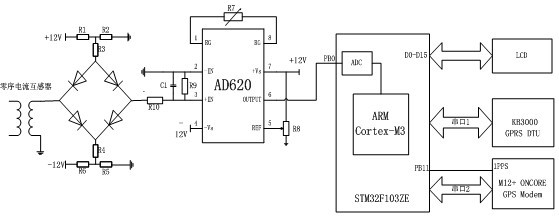
[0015] The schematic diagram of the line selection device used in the present invention is shown in image 3 , the zero-sequence voltage / current in the figure passes through the transformer and first passes through the limiting circuit to remove the impact voltage, and then enters the AD736 to adjust the signal, and the adjusted signal is input to the ADC. The GPS provides the CPU with the second pulse and time. After receiving the second pulse, the CPU reads the signal converted by the ADC and then calculates the amplitude and phase of the zero-sequence current / voltage, and finally sends the amplitude and phase through GPRS.

[0016] The diagnostic description is as follows:

[0017] 1. Diagnosis method of bus PT wiring status

[0018] Whether the busbar PT wiring is correct or not is very important to the correct selection of the line selection device. Regardless of whether the line selection criteria of the line selection device are based on the zero-sequence current ...


PUM


Abstract

The invention relates to a state diagnosis method for a small-current ground fault line selection device, which comprises the following steps of: firstly, sequentially doing an instantaneous ground fault experiment for a plurality of lines connected on a bus by utilizing the small-current ground fault line selection device to be diagnosed, wherein if the lines of which zero-sequence current phases are lagged behind a zero-sequence voltage phase of the bus by 90 degrees are more than the lines of which the zero-sequence current phases are ahead of the zero-sequence voltage phase by 90 degrees in the ground fault experiment, the PT (Potential Transformer) connecting mode of the bus is correct, or the PT connecting mode of the bus is wrong; and then, on the premise of determining that the PT connecting mode of the bus is correct, according to a phase relation of a zero-sequence current of each line and a zero-sequence voltage of the bus of a substation, judging whether the CT connecting mode of each line is correct. According to the invention, the connecting fault of the small-current ground fault line selection device can be rapidly and accurately diagnosed and the debugging period of the line selection device is shortened, so that the maintenance cost of the line selection device is reduced.

Description

technical field [0001] The invention relates to a method for diagnosing whether there is a wiring error in a transformer of a single-phase grounding fault line selection device of a small current grounding system, and belongs to the technical field of testing. Background technique [0002] The 3kV-60kV distribution network widely adopts the neutral point non-effective grounding system, that is, the small current grounding system (see figure 1 ), when a single-phase ground fault occurs in the non-effectively grounded power grid, the other two phase-to-ground voltages rise to the line voltage, which threatens the insulation of the system, especially when intermittent arcing occurs, because there is no charge release path at the neutral point, it will cause Arcing to ground overvoltage, which in turn causes a phase-to-phase short circuit. Therefore, distribution network substation busbars are generally equipped with small current system line selection devices for detecting sin...

Claims


Application Information

Patent Timeline
Patent Type & Authority Applications(China)
IPC IPC(8): G01R31/02G01R31/08
CPCY04S10/52
Inventor 李刚郑顾平齐郑杨以涵田永超
Owner NORTH CHINA ELECTRIC POWER UNIV (BAODING)
Why Eureka
Try Eureka