Optical imaging system adopting free-form surface prism

An optical imaging system and curved prism technology, applied in optics, optical components, instruments, etc., can solve problems such as complex structure, unsuitable design needs, and heavy weight

Inactive Publication Date: 2012-07-11
黄志奇 +2
View PDF3 Cites 10 Cited by
  • Summary
  • Abstract
  • Description
  • Claims
  • Application Information

AI Technical Summary

Problems solved by technology

The traditional optical system has many optical components, complex structure, and heavy weight, which causes a great burden on the head, and the optical path is long, the imaging quality is reduced, the field of view is also small, and they are all non-see-through structures, which are not suitable for today Head-mounted display designs require

Method used


Image

  • Optical imaging system adopting free-form surface prism
  • Optical imaging system adopting free-form surface prism
  • Optical imaging system adopting free-form surface prism

Examples


Embodiment Construction

[0017] Describe in detail below in conjunction with accompanying drawing.

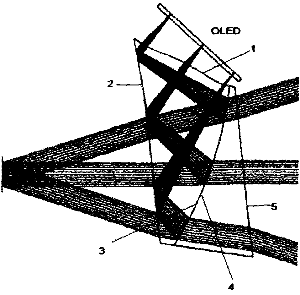
[0018] In the present invention, the default coordinate system is set as: the positive direction of the z-axis is to the right, the positive direction of the y-axis is upward, and the positive direction of the x-axis is the vertical plane inward.

[0019] The light is emitted by the OLED and refracted from surface 1 into the optical system. The incident angle on surface 2 is greater than the total reflection angle, so all the light is reflected to surface 3. Since surface 3 is coated with a part of the semi-reflective and semi-permeable film, part of the light is reflected to Surface 2, at this time, the incident angle is smaller than the total reflection angle, and the light can be refracted into the human eye. The external light can enter the optical system through the surface 5, and the surface 5 is parallel to the surface 2, which largely eliminates the deviation and inclination of the light.

[0...


PUM

PropertyMeasurementUnit
viewing angleaaaaaaaaaa

Abstract

The invention belongs to the technical field of virtual reality and particularly relates to an optical system applied to various virtual displayer products, such as glasses type virtual displayers, head-mounted virtual displayers and virtual stereoscopic displayers. The optical system comprises a free curved-surface prism and a compensator prism, wherein the top end of the optical system is provided with a micro displayer which is connected with video equipment through a driving circuit board for image display. Three optical surfaces of the free curved-face prism are all free curved faces and meet corresponding facial form equations, and the position relation among all the surfaces meets a corresponding coordinate conversion equation. The optical system is made of a PMMA plastic material, has the advantages of light weight, large view field, perspective property, favorable aberration correction performance and the like, and can present a clear magnified image in front of the eyes of people.

Description

technical field [0001] The invention relates to an optical imaging system using a free-form surface prism, belonging to the field of optical design. The optical imaging system is installed inside the head-mounted display. Background technique [0002] Head-Mounted Display (HMD) evolved from Head-Up Display (HUD) and was first used for military purposes. The head-mounted display consists of three parts: circuit system, optical system and support system. The earliest head-mounted displays used cathode ray tubes as image sources. With the advancement of technology, they have been replaced by silicon-based liquid crystals and organic light-emitting diodes. The integration of circuits is getting higher and higher, and the technology in this area is relatively mature. To realize the light weight and miniaturization of the head-mounted display, the design of the optical system becomes particularly important. The traditional optical system has many optical components, complex str...

Claims


Application Information

Patent Timeline
Patent Type & Authority Applications(China)
IPC IPC(8): G02B27/00G02B27/01G02B17/08G02B1/04G02B1/10
Inventor 黄志奇陈东义卢东杰
Owner 黄志奇
Why Eureka
Try Eureka