Touch display device

A touch display device and touch sensing technology, applied in static indicators, instruments, computing, etc., can solve problems such as difficulty in conforming to thin shape, cumbersome assembly process, and increased assembly thickness, so as to reduce manufacturing costs and finished products Thickness, reduced packaging and shipping costs, and reduced assembly man-hours

Inactive Publication Date: 2012-07-11
YOUNG LIGHTING TECHNOLOGY INC
View PDF6 Cites 21 Cited by
  • Summary
  • Abstract
  • Description
  • Claims
  • Application Information

AI Technical Summary

Problems solved by technology

However, the above-mentioned assembling process is cumbersome and labor-intensive, and when the capacitive touch element 102 is assembled to the liquid crystal display module 110, the outer edge of the visible area needs to be additionally insulated with a buffer material 118 (such as silicone resin or foam, etc.). To avoid foreign matter entering and producing bright lines
In addition, there needs to be a gap G between the capacitive touch element 102 and the liquid crystal display module 110, otherwise, electrostatic adsorption between the capacitive touch element 102 and the liquid crystal display module 110 will easily occur, resulting in Newton rings and affecting the image performance. The gap G will cause the assembly thickness to increase
Furthermore, the above design needs to use the black frame area of ​​the cover mirror 104 to cover the metal wiring of the capacitive touch element 102. If the cover mirror 104 is not used, the thickness of the front case 108 must be increased to cover the metal wiring, which is difficult to meet The need for thinner

Method used


Image

  • Touch display device
  • Touch display device
  • Touch display device

Examples


Embodiment Construction

[0064] The aforementioned and other technical contents, features and effects of the present invention will be clearly presented in the following detailed description of the embodiments with reference to the drawings. The directional terms mentioned in the following embodiments, such as: up, down, left, right, front or back, etc., are only referring to the directions of the drawings. Accordingly, the directional terms used are illustrative and not limiting of the invention.

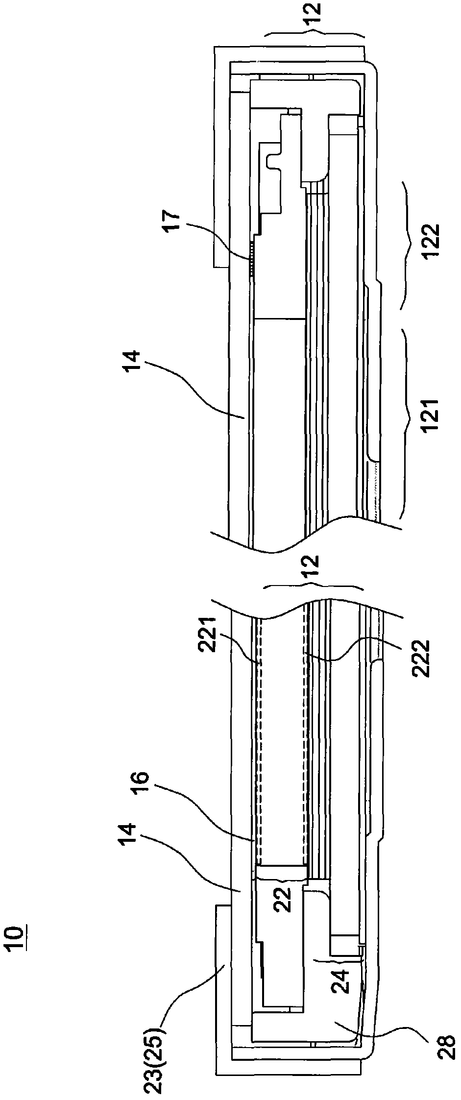
[0065] Such as figure 2As shown, the touch display device 10 includes a liquid crystal display module 12 and a touch sensing element 14 . The liquid crystal display module 12 may include, for example, a liquid crystal panel 22 and a backlight module 24 disposed on one side of the liquid crystal panel 22 . The liquid crystal display module 12 includes a visible area 121 and a non-visible area 122 . The touch sensing element 14 is placed on the liquid crystal display module 12 and attached to the upper s...


PUM


Abstract

The invention discloses a touch display device which comprises a liquid crystal display module and a touch sensing element, wherein the touch sensing element is attached to one surface of the liquid crystal display module.

Description

technical field [0001] The invention relates to a touch display device. Background technique [0002] figure 1 It is a partial cross-sectional schematic diagram of a conventional touch display device. Such as figure 1 As shown, the touch display device 100 has a capacitive touch element 102, and the capacitive touch element 102 is fixed on the bottom of a cover lens (cover lens) 104 by using optical glue (not shown), and the cover lens 104 uses high viscosity The double-sided adhesive tape 106 is pasted on the front case 108 . After these components are assembled, the liquid crystal display module 110 and the back case 112 are combined to form the touch display device 100 . The liquid crystal display module 110 may include a liquid crystal panel 114 and a backlight module 116 , for example. However, the above-mentioned assembling process is cumbersome and labor-intensive, and when the capacitive touch element 102 is assembled to the liquid crystal display module 110, the ...

Claims


Application Information

Patent Timeline
Patent Type & Authority Applications(China)
IPC IPC(8): G06F3/041G02F1/133
CPCG06F3/044G06F3/0412G06F3/0443
Inventor 黄维正戴立群林殷任
Owner YOUNG LIGHTING TECHNOLOGY INC
Why Eureka
Try Eureka