
Method for monitoring mine gas

A gas monitoring and mine technology, applied in special data processing applications, instruments, biological neural network models, etc., can solve problems such as reliability, poor real-time performance, loss of detection ability, measurement data deviation, etc., and achieve the effect of redundancy

Inactive Publication Date: 2012-07-11
SHANGHAI DIANJI UNIV
View PDF0 Cites 9 Cited by
  • Summary
  • Abstract
  • Description
  • Claims
  • Application Information

AI Technical Summary

Problems solved by technology

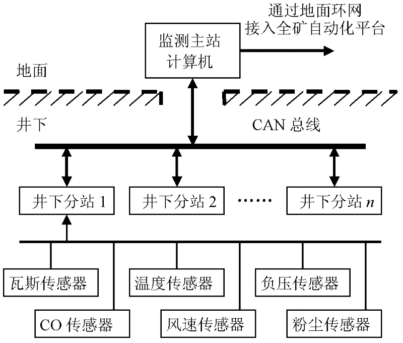
like figure 1 As shown, it includes a plurality of different types of sensors for monitoring the main station computer and each substation in the underground, such as: gas sensor, temperature sensor, negative pressure sensor, CO sensor, wind speed sensor and dust sensor, etc. It can be seen that the prior art The mine gas monitoring system needs to use a large number of different types of sensors, but due to the limitation of sensor measurement accuracy and the interference of environmental factors, there will be deviations between the measured data and the actual situation. What is more serious is that the erosion of harmful gases in the complex underground environment will make the Some sensors lose their ability to detect
Many traditional solutions are to use a single sensor to perform multiple measurements or take the average value of multiple sensor measurement data. Although this can improve the reliability of the measurement and control system to a certain extent, it cannot meet the real-time requirements of the system. Inaccurate measurement The data will still affect the final judgment
[0003] To sum up, it can be seen that the mine gas monitoring method of the prior art has the problems of poor reliability and real-time performance, so it is necessary to propose improved technical means to solve this problem

Method used


Image

  • Method for monitoring mine gas
  • Method for monitoring mine gas
  • Method for monitoring mine gas

Examples


Embodiment Construction

[0029] The implementation of the present invention is described below through specific examples and in conjunction with the accompanying drawings, and those skilled in the art can easily understand other advantages and effects of the present invention from the content disclosed in this specification. The present invention can also be implemented or applied through other different specific examples, and various modifications and changes can be made to the details in this specification based on different viewpoints and applications without departing from the spirit of the present invention.

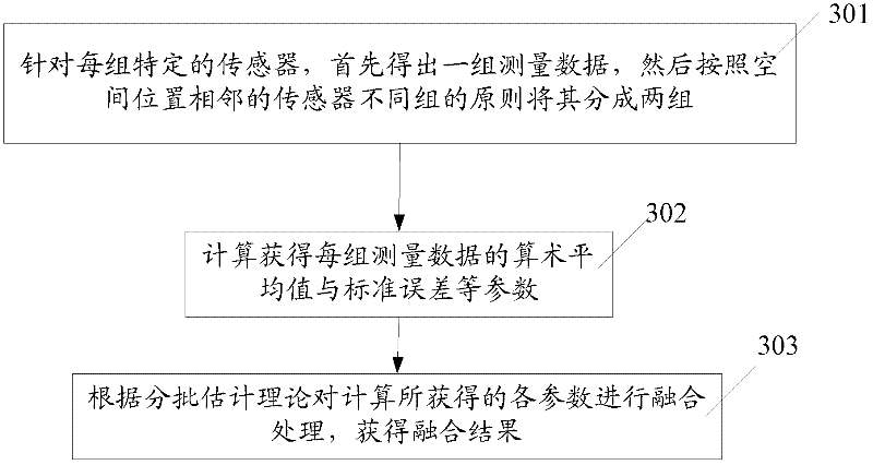
[0030] figure 2 It is a flow chart of the steps of a mine gas monitoring method of the present invention, which is applied to figure 1 The mine gas monitoring system includes at least the following steps:

[0031] In step 201, each parameter of the same sensor from different sub-stations is fused by using the batch estimation theory to obtain a more accurate fused result (measurement resu...


PUM


Abstract

The invention discloses a method for monitoring mine gas. The method comprises the following steps of: fusing all parameters of the same kind of sensors from different substations by using a patch estimation theory to acquire an accurate first-stage fusion result; comprehensively processing the first-stage fusion result by using a back propagation (BP) neural network; and acquiring underground environment information, and performing safety evaluation. The data of underground sensors is subjected to two-stage fusion by using the patch estimation theory and the BP neural network, so that a measuring error is reduced to a great extent, the accuracy of the data is improved, the gas distribution condition of an underground coal mine is accurately reflected, the monitoring speed and reliability of the gas are improved, and the fused sensor information has redundancy, complementarity and real-time property.

Description

technical field [0001] The invention relates to a mine gas monitoring method, in particular to a mine gas monitoring method based on multi-information fusion. Background technique [0002] With the increase of coal mine mining depth, the diversity of underground geological conditions, the complexity of gas occurrence and the uncertainty of gas outburst become more significant, which poses great safety hazards in coal mine safety production. Mine gas monitoring is mainly for real-time detection of underground gas and CO concentration, dust content, temperature, wind speed, negative pressure and other parameters. figure 1 It is a system architecture diagram of a mine gas monitoring system in the prior art. Such as figure 1 As shown, it includes a plurality of different types of sensors for monitoring the main station computer and each substation in the underground, such as: gas sensor, temperature sensor, negative pressure sensor, CO sensor, wind speed sensor and dust sensor...

Claims


Application Information

Patent Timeline
Patent Type & Authority Applications(China)
IPC IPC(8): G06F19/00G06N3/02
Inventor 王海军
Owner SHANGHAI DIANJI UNIV
Learn More