
Burner with chip test function and burning method thereof

A technology of chip testing and burning machine, which is applied in the direction of measuring electricity, measuring devices, measuring electrical variables, etc. It can solve problems such as chip insertion error, burning, pin burning, etc., and achieve the effect of preventing code readback and verification errors

Active Publication Date: 2012-07-11
CRM ICBG (WUXI) CO LTD
View PDF5 Cites 19 Cited by
  • Summary
  • Abstract
  • Description
  • Claims
  • Application Information

AI Technical Summary

Problems solved by technology

In actual use, operators often have errors such as reverse chip insertion and wrong chip insertion. Once some chips are inserted reversely, it will cause a short circuit between the programming power supply and ground. If there is no corresponding If the circuit is protected, it will often burn some components of the burner
Moreover, when some OTP chips are programmed and read back in the programming mode, it is necessary to add a high-voltage enable signal above 10V to a certain pin. Once the chip is inserted reversely or wrongly inserted, the high-voltage signal will be added to the on other pins, it will cause the pin to be burned
At the same time, if some OTP chips are encrypted and protected in the programming mode, the original code cannot be read back in the programming mode. If you need to read back the original program at this time, you need to go to the testing department to read it out with a tester.

Method used


Image

  • Burner with chip test function and burning method thereof
  • Burner with chip test function and burning method thereof
  • Burner with chip test function and burning method thereof

Examples


Embodiment Construction

[0033] The present invention will be further described below according to accompanying drawing and specific embodiment:

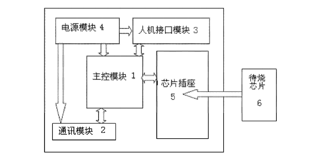
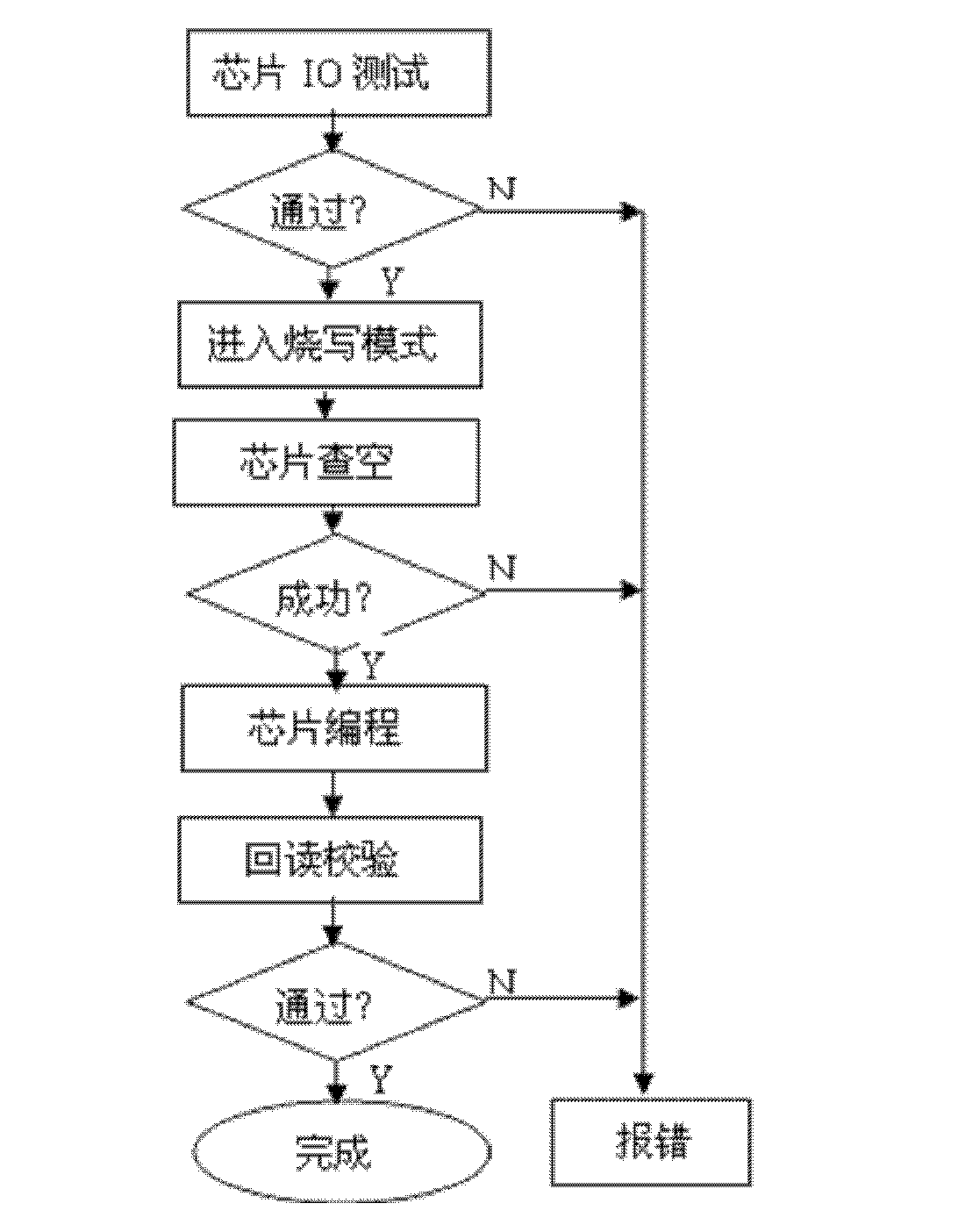
[0034] Such as figure 1 As shown, the burner with chip testing function of the present invention includes a main control module 1, a communication module 2, a human-machine interface module 3 and a power supply module 4 that provides power to the above modules, and the main control module 1 is responsible for the communication module. 2. Control sending and receiving, save communication data, and be responsible for the interaction of the human-computer interaction module 3, and be responsible for programming and testing the sequence of the chip outside the chip. The burner also includes a chip socket 5, which passes the pin It is directly connected to the main control module 1, and the chip to be burned is inserted into the chip socket 5 and controlled by the main control module 1. There are pins used for testing at the end of the chip socket 5, and the tes...


PUM


Abstract

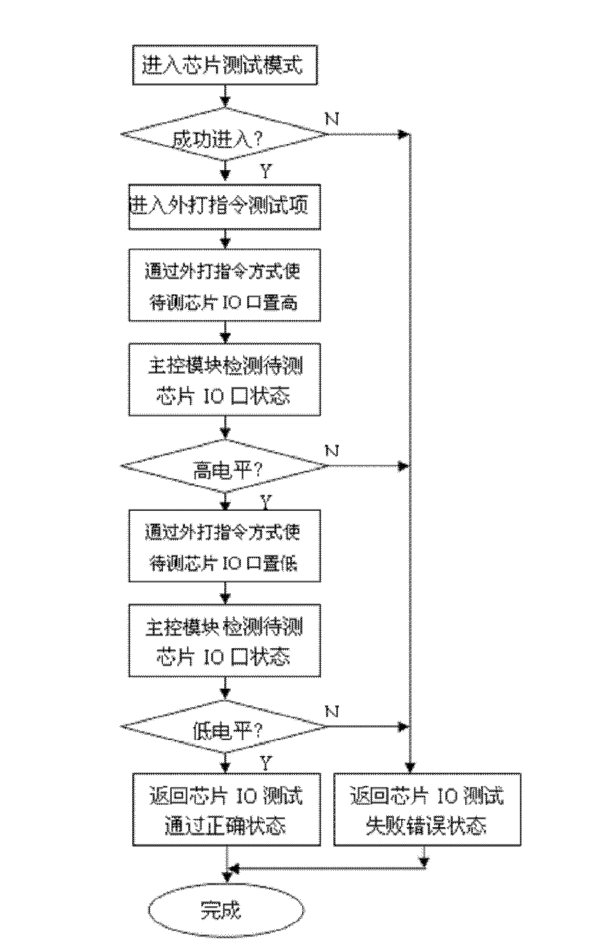
The invention discloses a burner with chip test function and a burning method of the burner. The burner comprises a main control module, a communication module, a human-machine interface module and a power supply module that provides a power supply to the above modules. The main control module is mainly used to control sending, receiving and storing communication data for the communication module and to interact with the human-machine interface module. The burner further comprises a chip socket connected with the main control module through a burning pin. A chip to be burned is inserted into the chip socket and controlled by the main control module. The pin for test is introduced from the chip socket end. The pin for test is further connected with the main control module. The main control module comprises a chip IO test program that monitors whether the IO interface of the chip to be burned can be placed in a high position and a low position under a test mode or not. The invention can eliminate conditions such as misplugging of the chip, reversed plugging and the like, and ensures that the chip to be burned and the internal elements in the burner are free from overburning.

Description

technical field [0001] The invention relates to a burning machine with a chip testing function and a burning method thereof. Background technique [0002] Currently, most programmers only support operations such as chip blank checking, programming, and verification. In actual use, operators often have errors such as reverse chip insertion and wrong chip insertion. Once some chips are inserted reversely, it will cause a short circuit between the programming power supply and ground. If there is no corresponding If the protection circuit is used, some components of the burner will often be burned. Moreover, when some OTP chips are programmed and read back in the programming mode, it is necessary to add a high-voltage enable signal above 10V to a certain pin. Once the chip is inserted reversely or wrongly inserted, the high-voltage signal will be added to the On other pins, it will cause the pin to be burned. At the same time, if some OTP chips are encrypted and protected in ...

Claims


Application Information

Patent Timeline
Patent Type & Authority Applications(China)
IPC IPC(8): G11C16/10G01R31/02
Inventor 潘杰王会刚
Owner CRM ICBG (WUXI) CO LTD
Learn More