Pay-off stand for motor compensating winding

A technology for compensating windings and pay-off racks, which is applied to electric components, manufacturing motor generators, electrical components, etc., and can solve the problem of electromagnetic wire outsourcing insulation damage, large footprint of pay-off racks, and cold work of flat copper wires inside electromagnetic wires. Hardening and other problems to ensure the insulation performance and improve the quality of the whole machine

Inactive Publication Date: 2012-07-11
襄阳中车电机技术有限公司
View PDF5 Cites 10 Cited by
  • Summary
  • Abstract
  • Description
  • Claims
  • Application Information

AI Technical Summary

Problems solved by technology

[0002]At present, when the known winding of the stator compensation winding of the traction motor of the railway locomotive is made, the form of the pay-off frame is mainly a multi-row wheel extrusion type, and its disadvantages Mainly include: ① When winding, the magnet wire must be squeezed by multiple rows of wheels, which may easily cause damage to the insulation of the magnet wire; The flat copper wire is hardened by cold work, which affects the forming of the subsequent coil; ③The pay-off frame occupies a large area

Method used


Image

  • Pay-off stand for motor compensating winding
  • Pay-off stand for motor compensating winding

Examples


Embodiment Construction

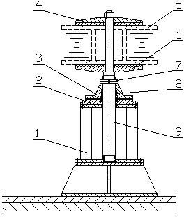
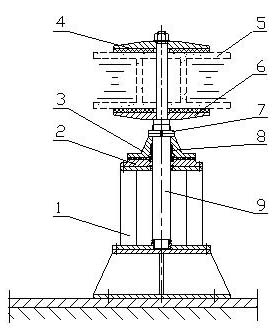
[0012] Such as figure 1 As shown, a pay-off rack rotating shaft 9 is fixed on the pay-off rack rotating shaft support frame 1, and the rotating shaft 9 is fixed on the support frame 1 through two sliding bearings and a plane thrust bearing, and an electromagnetic wire reel 5 is fixed on the upper end of the rotating shaft 9 , the upper and lower ends of the electromagnetic wire reel 5 are clamped and fixed on the rotating shaft 9 by the wire crimping disc 4 and the wire supporting disc 6 respectively, and can rotate together with the rotating shaft 9. Between them, rubber gaskets are lined between the electromagnetic wire reel 5 and the wire tray 6; a brake device is connected on the rotating shaft 9, and the brake device includes a friction disc 3 and a brake pad, and the friction disc 3 is connected to the shaft by a key. On the rotating shaft 9, a spring 8 is installed between the inner circle of the friction moving disk 3 and the rotating shaft 9, and the lower end surfac...


PUM


Abstract

The invention discloses a pay-off stand for a motor compensating winding, relating to the industry of motor production, in particular to a special tool for producing a motor stator compensating winding. The pay-off stand mainly solves the problems that existing multi-row wheel squeezing-pulling type pay-off stands cause damage and intersected deformation of the external insulation of an electromagnetic wire, affect subsequent coil formation and occupy a large area. The rotating shaft of the pay-off stand is connected on a support frame by a bearing, an electromagnetic wire coiling wheel is clamped and fixed on the rotating shaft by a wire support plate and a wire pressing plate, and a brake device of the rotating shaft is connected on the rotating shaft. The pay-off stand cannot damage the electromagnetic wire during the coiling of the compensating winding, can ensure the insulating property of coils of the motor compensating winding and improves the motor quality. The pay-off stand is also applicable to the winding of other types of motor stator coils.

Description

technical field [0001] The invention relates to a motor manufacturing industry, in particular to a special tool for manufacturing motor stator compensation windings. Background technique [0002] At present, when the known winding of the stator compensation winding of the traction motor of a railway locomotive is made, the form of the pay-off frame is mainly a multi-row wheel extrusion type, and its main disadvantages are: ①The electromagnetic wire must pass through multiple rows of wheels Extrusion can easily cause insulation damage to the outsourcing of the electromagnetic wire; ② During winding, the electromagnetic wire is squeezed by multiple rows of wheels and undergoes multiple alternating deformations, which causes the flat copper wire in the electromagnetic wire to undergo cold work hardening, which affects the forming of the subsequent coil; ③The pay-off frame occupies a large area. Contents of the invention [0003] The object of the present invention is to over...

Claims


Application Information

Patent Timeline
Patent Type & Authority Applications(China)
IPC IPC(8): H02K15/04
Inventor 潘则名
Owner 襄阳中车电机技术有限公司
Why Eureka
Try Eureka