
Combined power and timing signals for equipment

A technology of power signal and clock signal, which is applied in the field of circuits that generate power and timing signals, and can solve problems such as low efficiency and bulky isolation transformers

Active Publication Date: 2012-07-11
STMICROELECTRONICS (SHENZHEN) R&D CO LTD +1
View PDF7 Cites 6 Cited by
  • Summary
  • Abstract
  • Description
  • Claims
  • Application Information

AI Technical Summary

Problems solved by technology

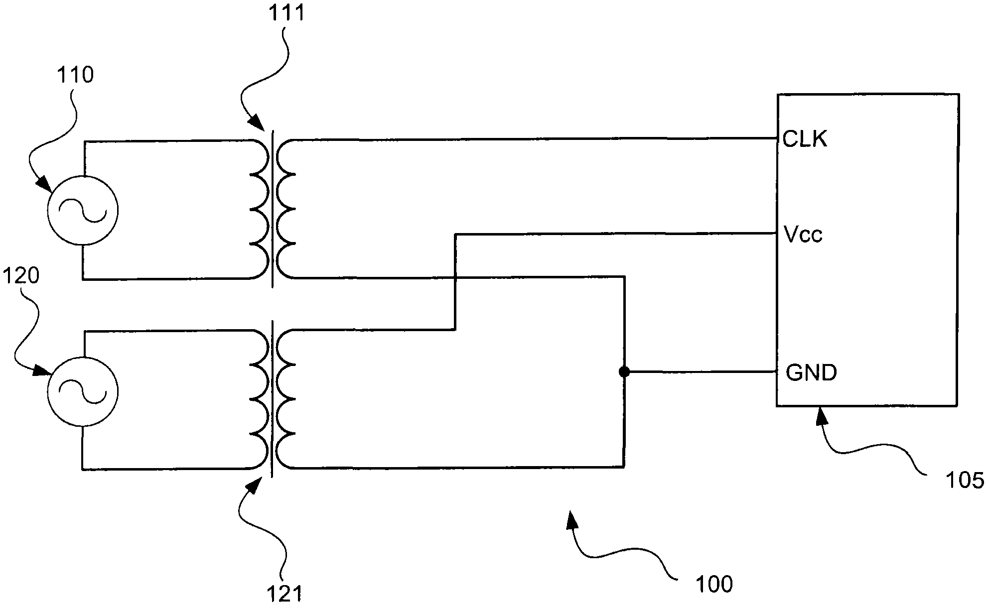
Providing two isolation transformers for these two sets of signals is bulky and inefficient

Method used


Image

  • Combined power and timing signals for equipment
  • Combined power and timing signals for equipment
  • Combined power and timing signals for equipment

Examples


Embodiment Construction

[0012] The following discussion is presented to enable any person skilled in the art to make and use the subject matter disclosed herein. The general principles described herein may be applied to other embodiments and applications than those detailed above without departing from the spirit and scope of the present specific embodiment. The present disclosure is not intended to be limited to the embodiments shown, but is to be accorded the widest possible scope consistent with the principles and features disclosed or suggested herein.

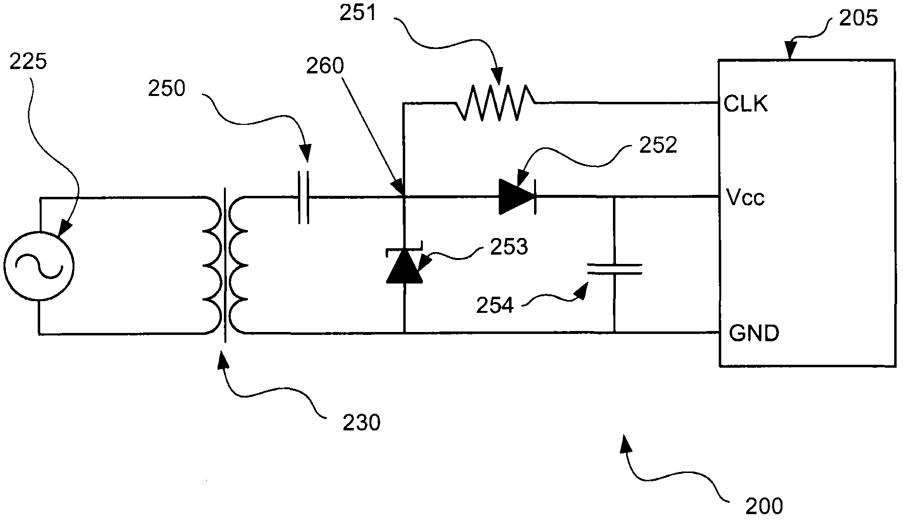
[0013] Before discussing the specific details of various implementations, an overview of one implementation of the subject matter is presented. Electronic circuits may often use the two types of signals discussed above—power signals and clock signals. According to various embodiments discussed below, a single signal may be used to provide both a power signal and a clock signal to a circuit via a single isolation transformer. In one embodiment, ...


PUM


Abstract

The invention relates to combined power and timing signals for equipment, in particular relates to combined power and timing signals in single electronic equipment. In one embodiment mode, a circuit can only comprise an isolation transformer, and the isolation transformer can be operated for generating a power signal and a timing signal. In a secondary side, two branches can be used for extracting the power signal and a clock signal which are used in a circuit on the isolated secondary side. The first branch can be coupled to the transformer, and can be operated for controlling a signal, such as a 5V direct-current signal, into the power signal. Similarly, the second circuit branch can be operated for controlling a signal, such as a 5V signal with 1MHz frequency, into the clock signal. Through extracting the power signal and the clock signal from the same isolation transformer at the secondary side, valuable space on integrated circuit equipment is saved due to a single winding used for the single isolation transformer.

Description

technical field [0001] The present invention relates to circuits and methods for generating power and timing signals, and three-phase metering systems. Background technique [0002] Systems and devices often rely on two types of signals to operate. Power signals can be used to provide power, logic, and control signals within a system or device. In addition, timing or clock signals may also be used to trigger, manipulate, or otherwise control various components and circuits of a system or device. Therefore, the two signals can be used together accordingly. [0003] Many times, a system or device may have the above-mentioned signals provided from outside the system or device. That is, the power signal and / or clock signal may come from a circuit external to the system or device. For example, when monitoring overhead power lines, the equipment used for monitoring may draw power directly from the power line itself. Similarly, in a device with multiple integrated circuit (IC)...

Claims


Application Information

Patent Timeline
Patent Type & Authority Applications(China)
IPC IPC(8): H02M5/10G01R21/06
CPCH02M2001/0064H02M7/068H02M1/0064G01R11/40G01R11/42H02M7/06
Inventor 葛绍献王慎张星
Owner STMICROELECTRONICS (SHENZHEN) R&D CO LTD
Learn More