Circuit for electrical isolation and clock synchronization and multi-channel signal generation device

A clock signal, electrical isolation technology, applied in the direction of electrical components, power automatic control, etc., can solve the problems of signal source current flow, application restrictions, non-isolation, etc., to achieve consistent phase and phase noise, and accurate phase and phase noise , Phase and Phase Noise Preservation Effect

Active Publication Date: 2012-07-11
RIGOL
View PDF4 Cites 3 Cited by
  • Summary
  • Abstract
  • Description
  • Claims
  • Application Information

AI Technical Summary

Problems solved by technology

like figure 1 As shown, in the case of non-isolation, some clock distribution chips with electrical connections are used, such as MC100E210FNG and MC100EL14DWG of ONSEMI, etc., through which the chip can only be used in the case of non-isolation. , phase and phase noise are exactly the same effect
[0004] The inventor found in the process of realizing the present invention that the prior art has the following deficiencies: on the one hand, the output channels of the multi-channel signal source in the prior art are all non-isolated, although it has been realized that the channels between the non-isolated The frequency, phase and phase noise are exactly the same, but because its output channels are non-isolated, its application is greatly limited
For example, in the case of non-isolation, when different channels of the signal source are connected to different electrical equipment, if the potentials of different electrical equipment connected to different non-isolated channels are not the same, then it will cause the signal source and all There is a large current flowing between the connected equipment, which can easily damage the signal source itself and the electrical equipment connected to it
On the other hand, the existing technology cannot achieve the consistency of frequency, phase and phase noise between different channels when the output channels are completely electrically isolated

Method used


Image

  • Circuit for electrical isolation and clock synchronization and multi-channel signal generation device
  • Circuit for electrical isolation and clock synchronization and multi-channel signal generation device
  • Circuit for electrical isolation and clock synchronization and multi-channel signal generation device

Examples


Embodiment Construction

[0016] In order to make the purpose, technical solutions and advantages of the embodiments of the present invention clearer, the technical solutions in the embodiments of the present invention will be clearly and completely described below in conjunction with the drawings in the embodiments of the present invention. Obviously, the described embodiments It is a part of embodiments of the present invention, but not all embodiments. Based on the embodiments of the present invention, all other embodiments obtained by persons of ordinary skill in the art without making creative efforts belong to the protection scope of the present invention.

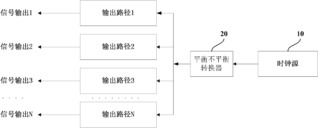
[0017] figure 2 It is a structural schematic diagram of a circuit for electrical isolation and clock synchronization according to an embodiment of the present invention. Such as figure 2 As shown, the circuit includes: a clock source 10, which is used to generate a clock signal; a balanced unbalanced converter 20, that is, Balun Balun, wh...


PUM


Abstract

The embodiment of the invention provides a circuit for electrical isolation and clock synchronization and a multi-channel signal generation device. The circuit comprises a clock source and a balance-unbalance converter, wherein the clock source is used for generating clock signals; the balance-unbalance converter is used for distributing the clock signals to a plurality of output paths, so that the frequency, the phase and the phase noise of clock signals obtained by the output paths are consistent with those of the clock signals produced by the clock source respectively; and the output paths are electrically isolated. The embodiment of the invention realizes the effect that the frequency, the phase and the phase noise of each output path are completely consistent under the condition that the output paths are mutually, completely and electrically isolated.

Description

technical field [0001] The invention relates to the field of measurement and testing, in particular to a circuit for electrical isolation and clock synchronization and a multi-channel signal generating device. Background technique [0002] At present, there are many DDS function arbitrary waveform signal generators on the market. These signal generators have not only one output channel (single channel), but also multiple output channels, such as dual channels and four channels. For signal generators with multi-channel output, the consistency of output frequency between channels and the consistency of phase noise output from different channels are very important. The current popular multi-channel signal generators on the market basically output channels between The channels are not electrically isolated. In this case, it is relatively easy to achieve the same frequency and related indicators (such as phase, phase noise, etc.) between the channels. However, if the output chann...

Claims


Application Information

Patent Timeline
IPC IPC(8): H03L7/06H03L7/085
Inventor 王悦王铁军李维森
Owner RIGOL
Why Eureka
Try Eureka