Microengineered self-releasing switch

a self-releasing switch and micro-engineered technology, applied in the field of switches, can solve the problems of excessive current demand, excessive size and cost of circuit breakers currently manufactured, and limited operation sophistication

Inactive Publication Date: 2005-07-07
YEATMAN ERIC
View PDF38 Cites 67 Cited by
  • Summary
  • Abstract
  • Description
  • Claims
  • Application Information

AI Technical Summary

Benefits of technology

[0022] Preferably, the switch further comprises a second current path associated with the second cantilever such that the passage of a second threshold electrical current through the second current path causes the second cantilever to flex from its rest position to its latched position. This enables the switch to be reset by the application of an electrical current.

Problems solved by technology

The excessive current demand will often be due to a failure in the system, such as a short circuit being formed by the failure of a component.
Never-the-less, both the size and cost of circuit breakers currently manufactured are excessive for some applications, and the sophistication of their operation is limited.
The control of the device, however, remains functionally separate from the electrical path which is switched, and thus an intrinsic circuit protection function is not provided.
These and other problems associated with the prior art means that there is a need for an electromechanical switch that can be re-settable in an efficient manner.

Method used


Image

  • Microengineered self-releasing switch
  • Microengineered self-releasing switch
  • Microengineered self-releasing switch

Examples


Embodiment Construction

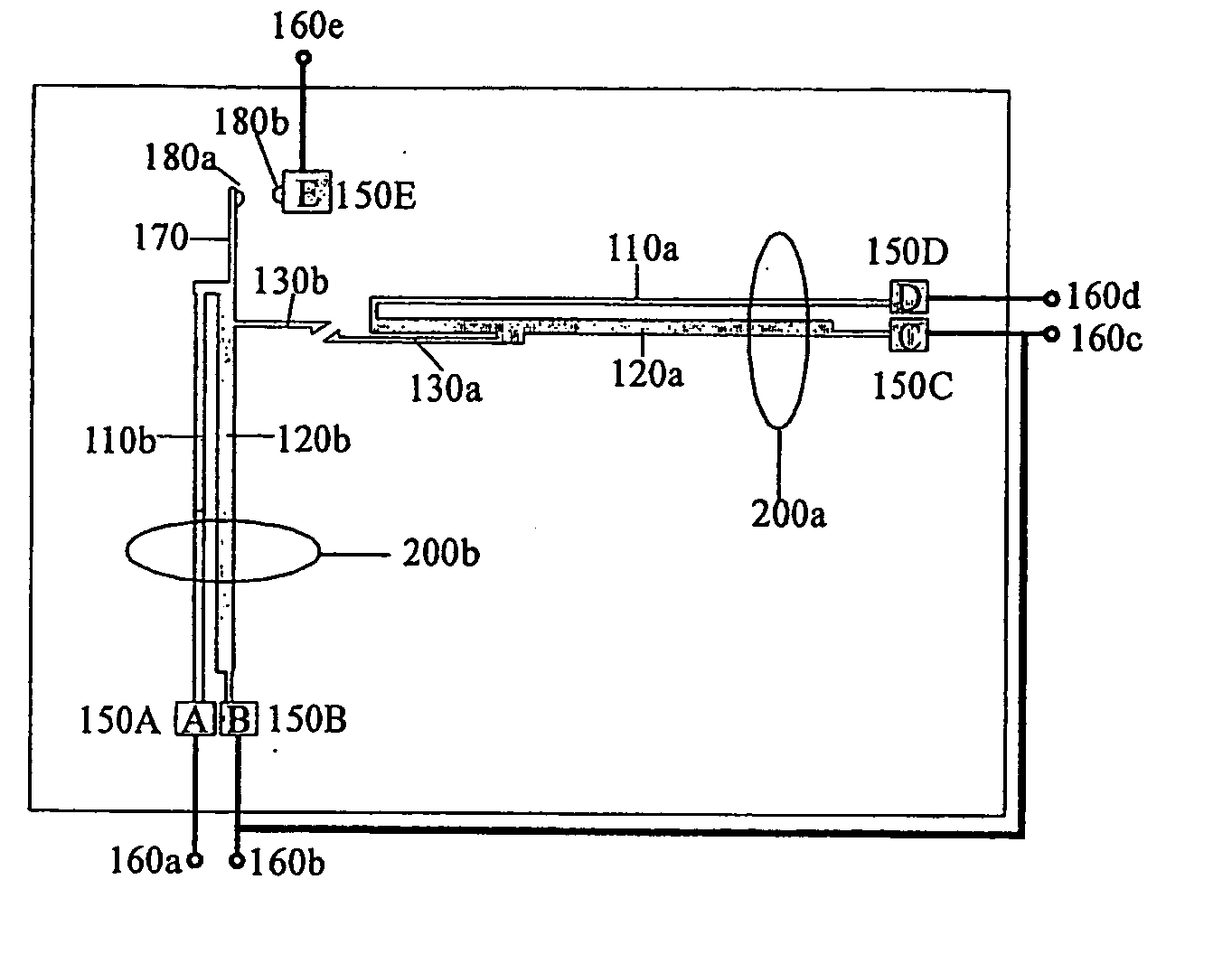
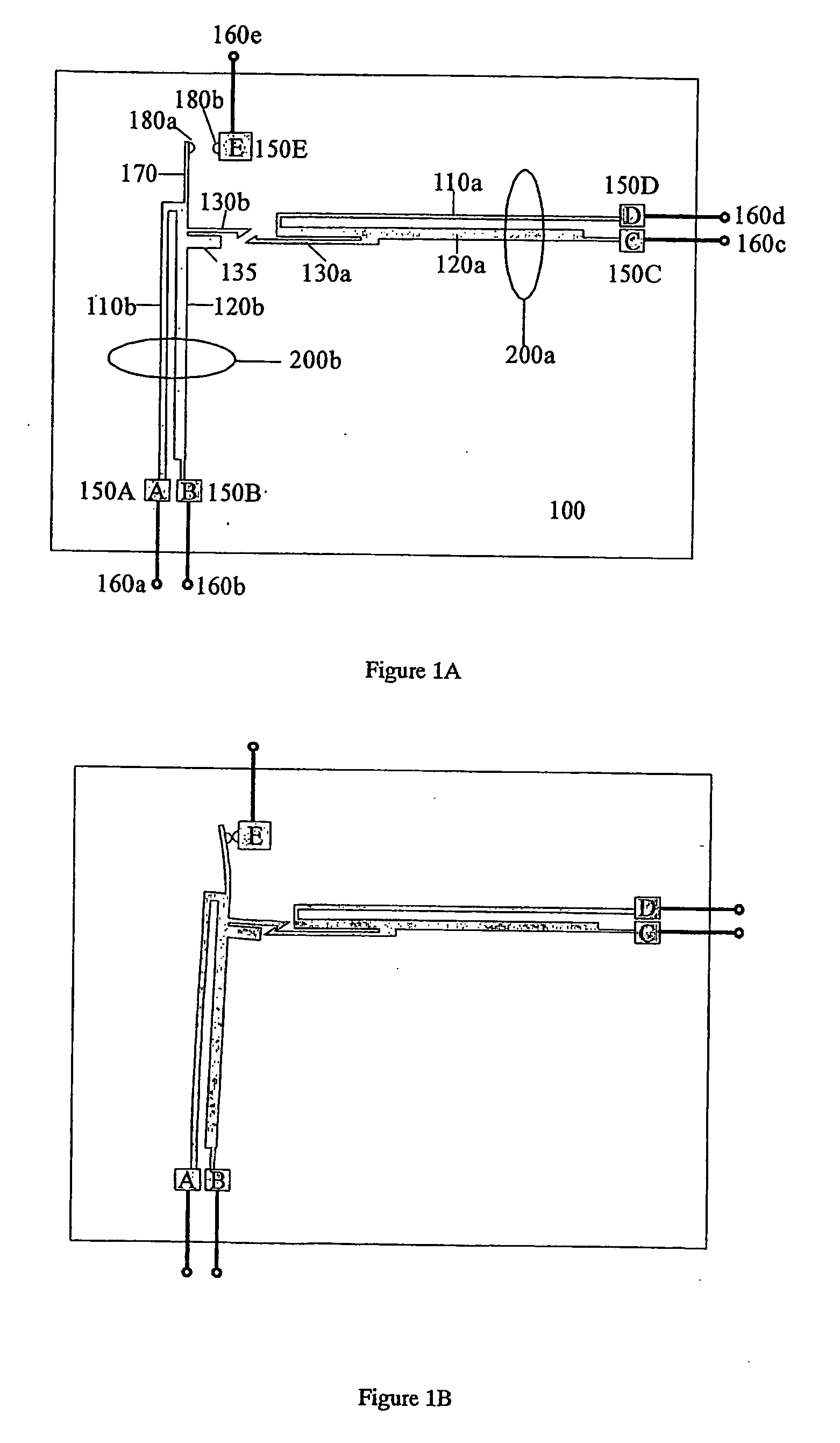
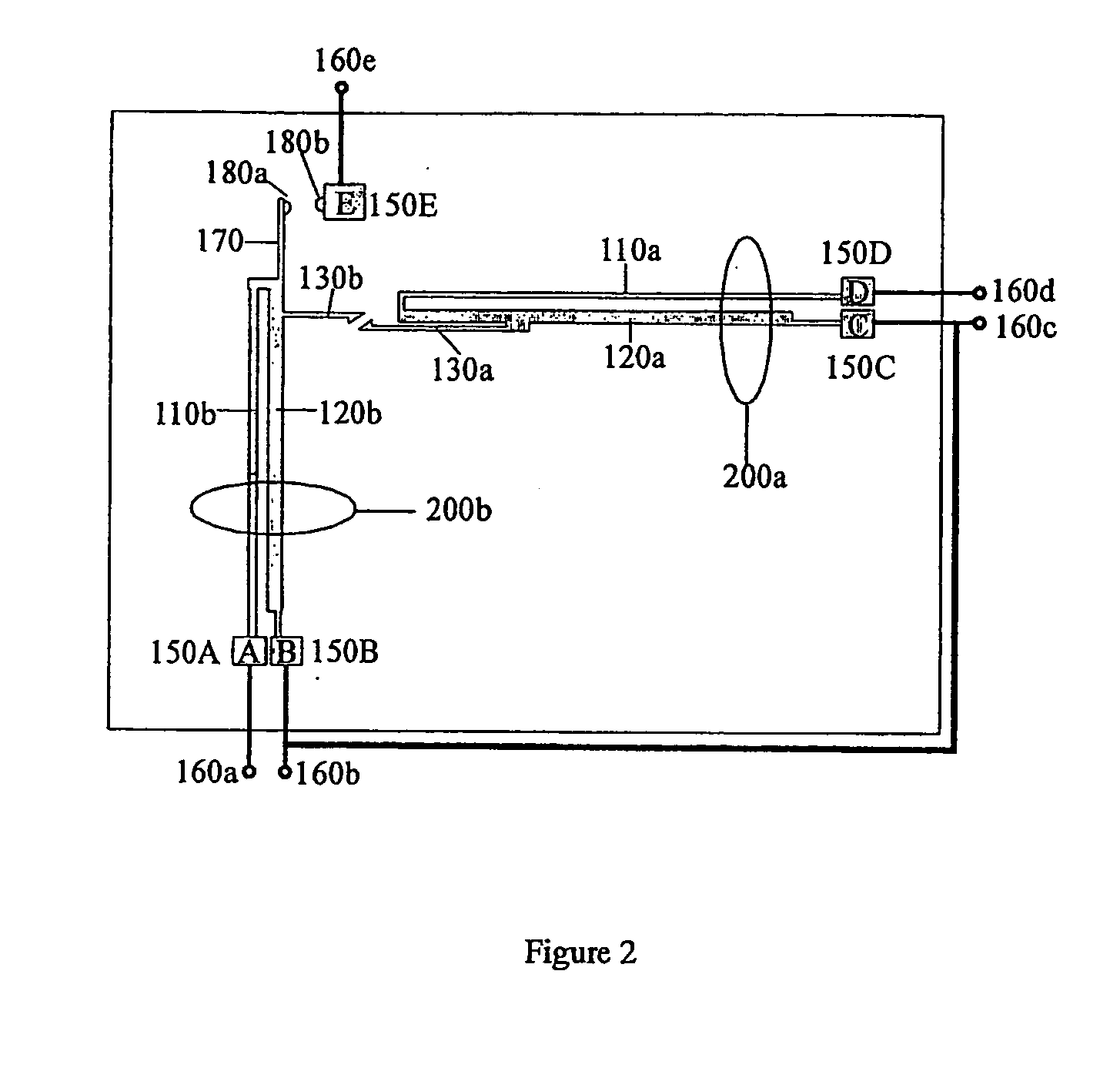
[0052] Referring in detail to the drawings where similar parts are identified by like reference numbers, there is seen in FIGS. 1A and 1B a diagram of a circuit breaking switch in its open and closed position respectively. The switch is mounted in such a way as to present a number of electrical terminals 160 for connection to a printed circuit board or otherwise for connection to external electrical circuits. These terminals could be for example the pins of a standard semiconductor package of a type used conventionally for mounting of integrated circuits on printed circuit boards. Terminals 160d and 160e provide the power supply and load connection respectively, such that the purpose of the switch is to prevent excess current levels from flowing from the supply to the load. Each external terminal 160 is electrically connected, for example by wire bonding, to a fixed anchor 150, each anchor being a part mechanically fixed to, but electrically isolated from, the substrate. The substra...


PUM


Abstract

A MEMS (microelectromechanical system) electrical switch device is provided for circuit protection applications. The device includes a mechanical latching mechanism by which the switch is held in the closed position, and a mechanism by which this latch is released when the load current passing through the device reaches or exceeds some desired magnitude. In addition, a mechanism is provided by which the switch may be reset to its closed position by applying an electrical control voltage to certain terminals of the device. A number of these devices, or arrays of these devices, can be fabricated by parallel processes on a single substrate, and photolithography can be employed to define the mechanical structures described above. Other embodiments include additional electrical isolation of the resetting mechanism, enhancement of the separation distance of the contact points of the switch in the open position, and prevention of arcing at the latch mechanism. A method of fabricating the device is provided. A method of using the aforementioned device is also provided.

Description

FIELD OF THE INVENTION [0001] The invention relates to switches and in particular to micro-engineered switches. More particularly the invention relates to types of switches that may self-release thereby enabling a circuit breaking functionality to be incorporated within the switch. BACKGROUND OF THE INVENTION [0002] Electrical circuits are frequently connected to a source of power in such a way that the connection is broken if the current drawn from the power supply exceeds some previously determined level. The excessive current demand will often be due to a failure in the system, such as a short circuit being formed by the failure of a component. Isolating the circuit in such a case may prevent or limit damage to the circuit itself, the power supply, or associated systems, and reduce the risk of fire or electrical shock. Isolation may be achieved by a fusible link or “fuse”, or by a reusable switch, generally known in this context as a circuit breaker. The fuse will generally be of...

Claims


Application Information

Patent Timeline
Patent Type & Authority Applications(United States)
IPC IPC(8): H01H1/00H01H61/02H01H71/14
CPCH01H1/0036H01H61/02H01H2061/008H01H2001/0047H01H2061/006H01H71/14
Inventor YEATMAN, ERIC
Owner YEATMAN ERIC
Why Eureka
Try Eureka