Electrically isolated shielded connector system

a shielded connector and shielded technology, applied in the direction of coupling device connection, coupling device details, coupling protective earth/shielding arrangement, etc., can solve the problems of increasing the effect, reducing the size, installation time, and increasing the cost of the cable and associated connectors, and inducing interference within

Inactive Publication Date: 2006-11-02
ORTRONICS INC
View PDF13 Cites 65 Cited by
  • Summary
  • Abstract
  • Description
  • Claims
  • Application Information

AI Technical Summary

Problems solved by technology

The non-use of cable shielding (e.g., a foil or braided metallic covering) in fabricating UTP cable generally increases the effects of outside interference, but also results in reduced cost, size, and installation time of the cable and associated connectors.
Ground loops may give rise to a current that induces interference within the cable, interference against that the shield was intended to protect.
The distortions are added by the transmission system, along with additional unwanted signals that are inserted somewhere between transmission and reception.
Noise is the major limiting factor in the performance of today's communication systems.
Problems that arise from noise include data errors, system malfunctions, and loss of the desired signals.
Generally, cross-talk noise occurs when a signal from one source is coupled to another line.
Utilizing FTP or mitigation cabling methods provide various issues and increase complexities.
In addition, FTP systems are considerably more expensive in material and installation cost.
As previously discussed, another issue with FTP is proper installation of system grounds.
Poor system grounding can create unwanted ground loops that could lead to increased system noise internally to the transmitter.
Mitigation of connectors in many cases is not an option since standard wall outlets (i.e. single gang electrical boxes) and 1 rack unit (typ.
1.5 inch) high mount panels are spaced limited from prior standards.

Method used


Image

  • Electrically isolated shielded connector system
  • Electrically isolated shielded connector system
  • Electrically isolated shielded connector system

Examples


Embodiment Construction

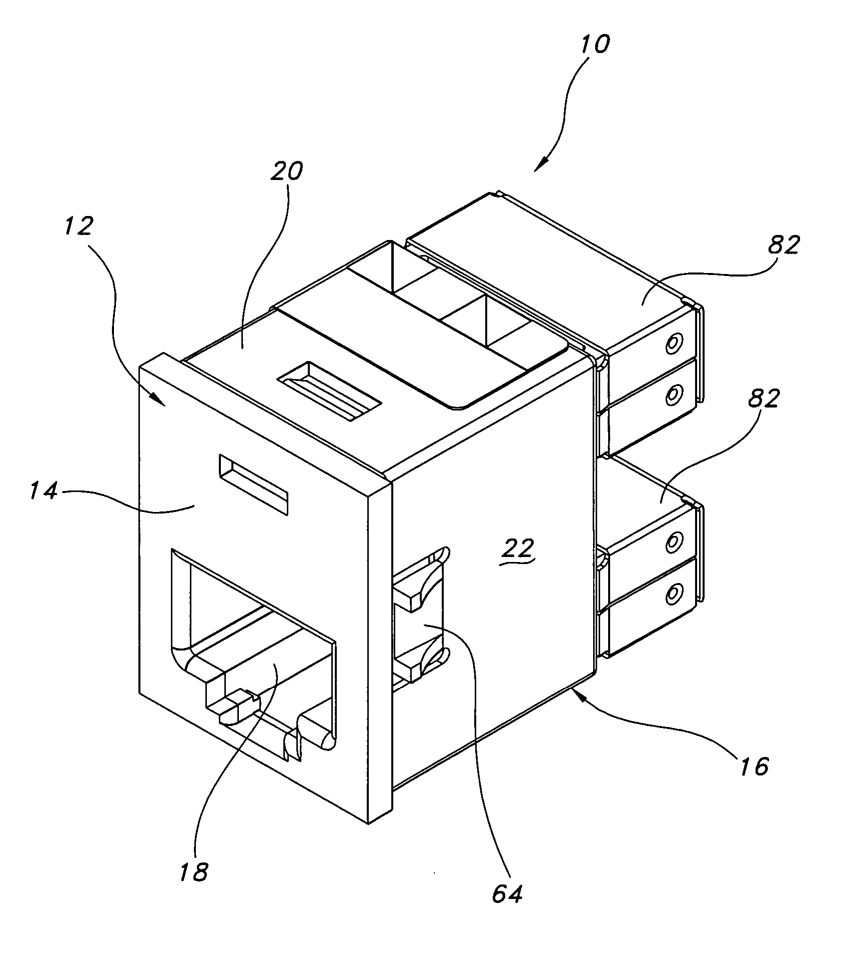
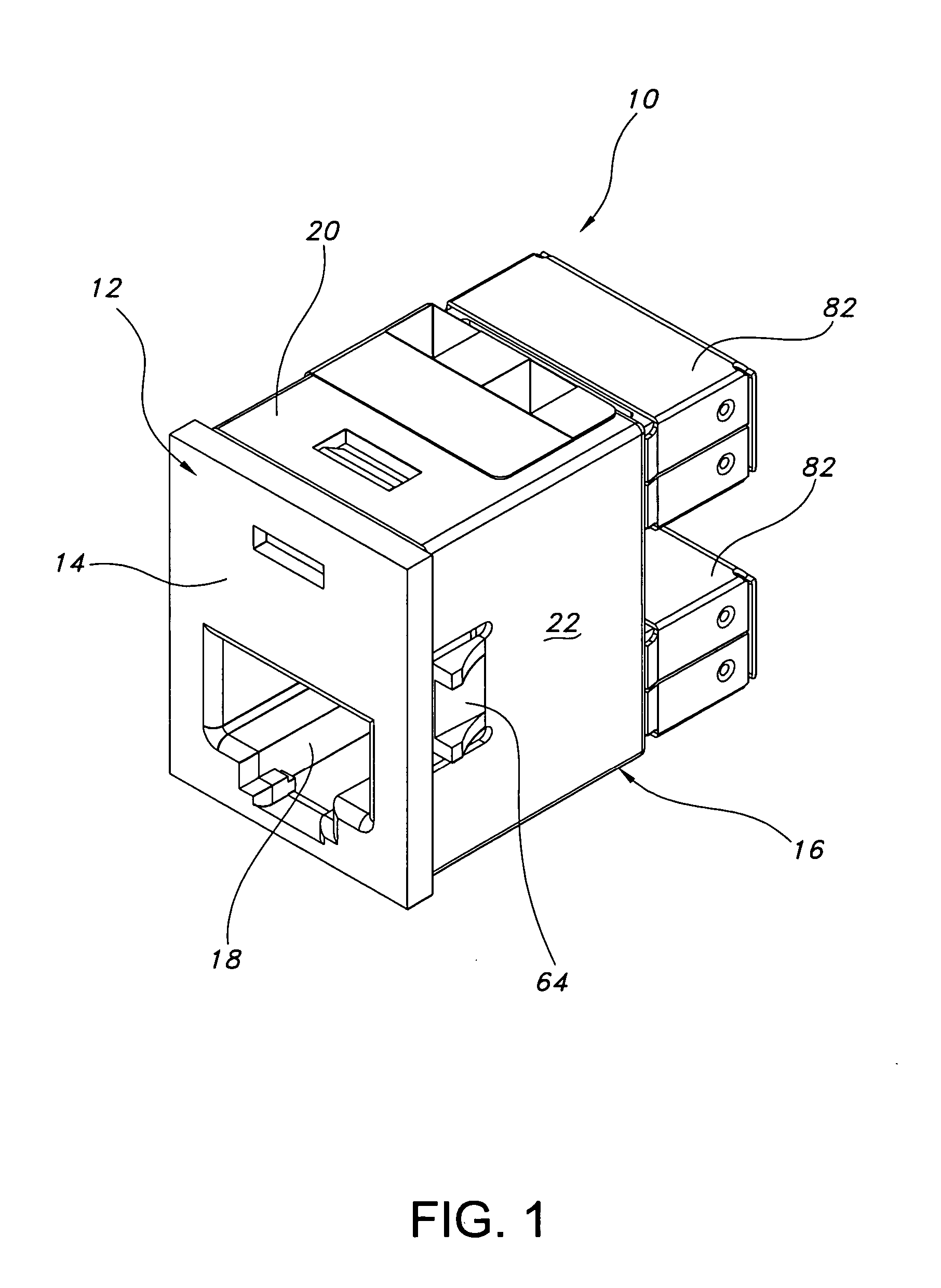
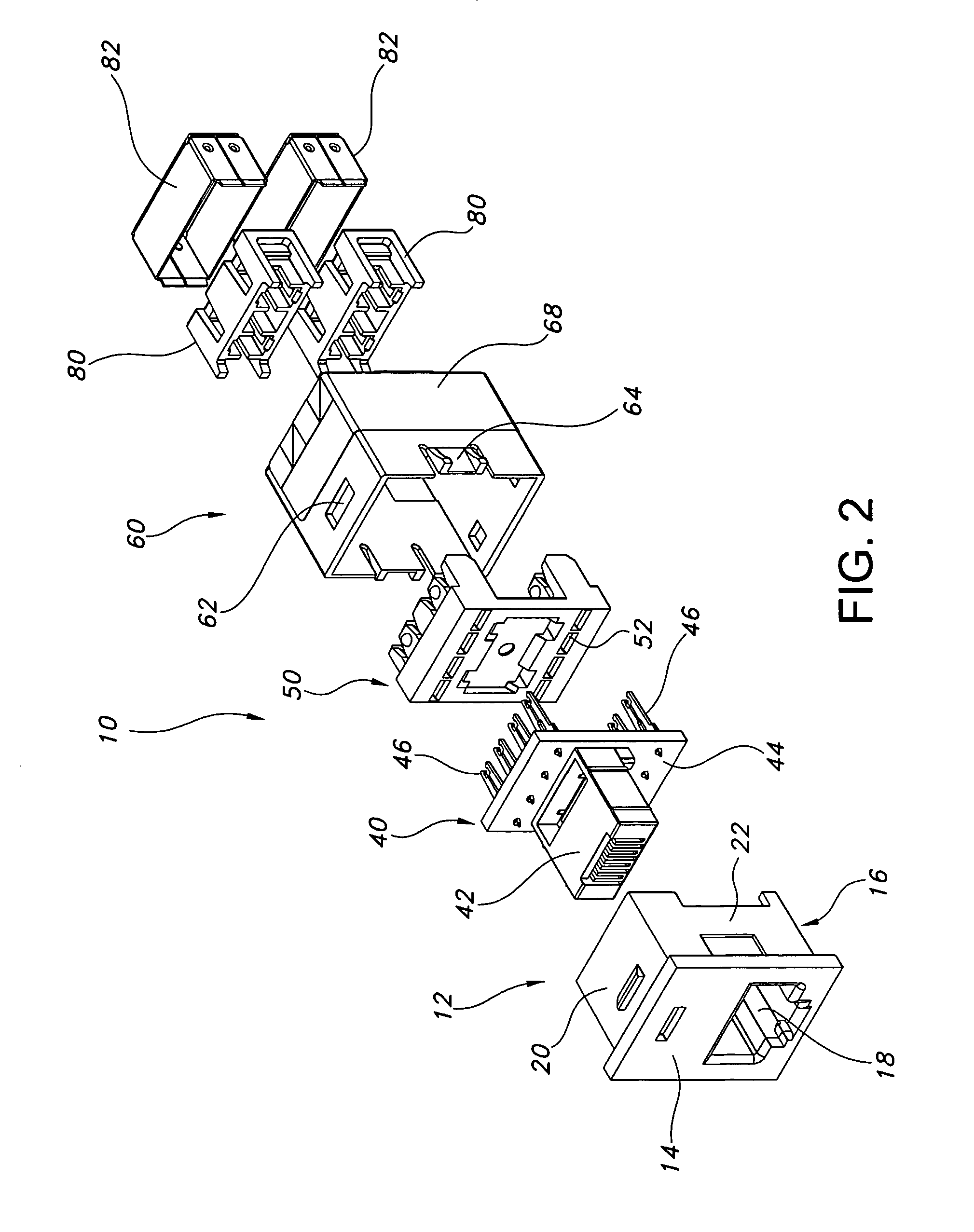
[0027] Referring to FIGS. 1-4, a connector 10 is illustrated. Connector 10 includes a front housing 12 that has a front face 14 and a main body 16. Front face 14 has a front opening 18 that is shaped to receive a telecommunication connector (not shown). Main body 16 has four sides (only three are shown) 20, 22, and 24. Sides 22 and 24 each have side openings 26 and 28. Side 20 has a notch 30. A back side 32 includes a back opening 34. Front housing 12 is made of engineering plastics, such as an ABS that is a copolymer of Acrylonitrile, Butadiene, and Styrene. ABS plastics generally possess medium strength and performance and at a reasonable cost that can be color coded to the customer's selection.

[0028] Connector 10 also includes a printed circuit board assembly (PCB) 40 that has a modular insert 42 that is slidably received into back opening 34. Modular insert 42 has a plurality of channel guilds for receiving contacts of the connector. Modular insert 42 contains terminals having ...


PUM


Abstract

The present disclosure is related to a multiport adapter for a telecommunication connector system that is designed to reduce EMI from outside sources, as well as, between adjacent ports by electrical isolation design. The reduction of EMI is done by non-conventional methods of connecting hardware shielding techniques. The shield design surrounds all the internal pairs within the plug housing to reduce the transmitted signals EM radiation during transmission and it does not make contact with the modular connector plug, horizontal cable or the plastic support adapter housing. By isolating each component in the interface system, the coupled radiated noise from each port to port shield is individually controlled.

Description

BACKGROUND OF THE INVENTION [0001] As Unshielded Twisted Pair (“UTP”) cabling continues to be an essential choice of media transmission, new and improved methods must be employed meet the requirements of the transmitting data source. UTP cable is a popular and widely used type of data transfer media. UTP cable is a very flexible, low cost media, and can be used for either voice or data communications. In fact, UTP cable is rapidly becoming the de facto standard for Local Area Networks (“LANs”), other in-building voice, and data communications applications. In an UTP, a pair of copper wires generally forms the twisted pair. For example, a pair of copper wires with diameters of 0.4-0.8 mm may be twisted together and wrapped with a plastic coating to form an UTP. The twisting of the wires increases the noise immunity and reduces the bit error rate (BER) of the data transmission to some degree. In addition, using two wires, rather than one, to carry each signal permits differential sign...

Claims


Application Information

Patent Timeline
Patent Type & Authority Applications(United States)
IPC IPC(8): H01R24/00
CPCH01R4/2433H01R13/506H01R13/518H01R13/5213H01R13/6658H01R13/748H01R24/64H01R13/6461H01R13/6586H01R13/659H01R13/6599H01R13/7193H05K1/0228
Inventor AEKINS, ROBERT A.HATHAWAY, ROBERT
Owner ORTRONICS INC
Why Eureka
Try Eureka