Electromagnetic heating coil plate

A technology of electromagnetic heating coils and coil disks, which is applied in the direction of coil devices and induction heating, etc., which can solve the problems of difficulty in dissipating heat at the jumper part, increase in preparation costs, and restrict the flexibility of winding operations, so as to simplify the structure and facilitate heat dissipation , to avoid the effect of heat accumulation

Active Publication Date: 2012-07-11
佛山市心静电磁科技有限公司
View PDF4 Cites 4 Cited by
  • Summary
  • Abstract
  • Description
  • Claims
  • Application Information

AI Technical Summary

Problems solved by technology

[0003] However, the structure disclosed in the above-mentioned patent is fixed in the hollow position in the middle of the wire jumper to realize the wire jumper of the enameled wire. Changing the mold increases the cost of mold preparation; at the same time, it also makes the structure of the coil support more complicated, and the enameled wire can only be jumped at the jumper part when winding the enameled wire, which greatly restricts the flexibility of the winding operation; moreover, In the above patented technical solution, a magnetic strip is installed on the back of the jumper part. During the working process of the coil disk, both the magnetic strip and the jumper part will generate a large amount of heat. This structure not only sets the jumper position on the magnetic strip At the top, all the jumper positions are also concentrated in the jumper part, which makes it difficult to dissipate the heat of the jumper part of the coil tray support, which in turn affects the normal operation of the coil tray

Method used


Image

  • Electromagnetic heating coil plate
  • Electromagnetic heating coil plate
  • Electromagnetic heating coil plate

Examples


Embodiment 1

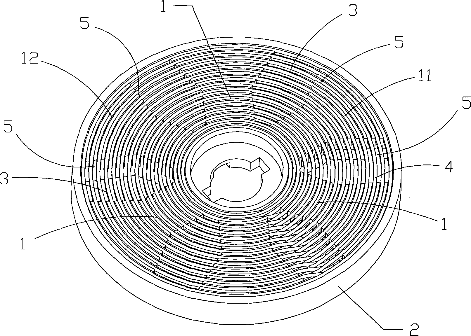
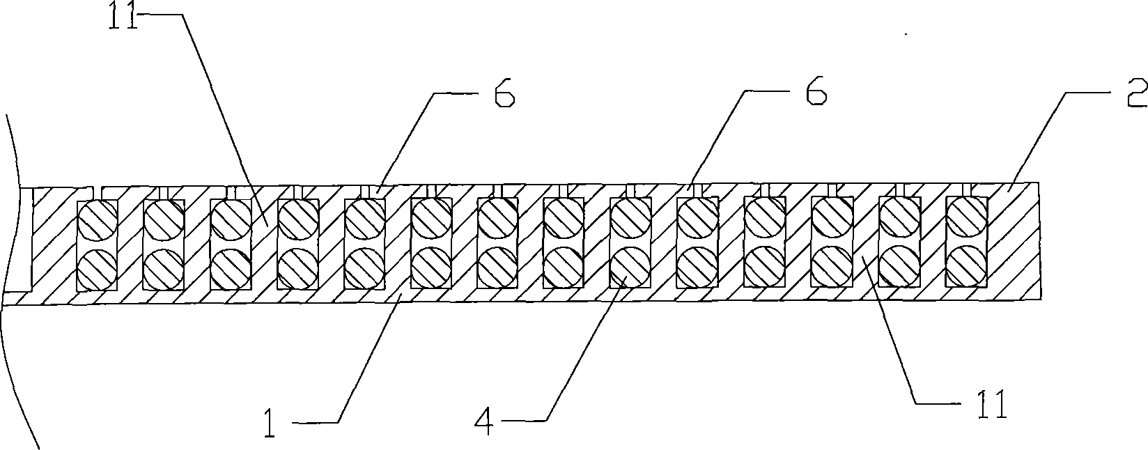
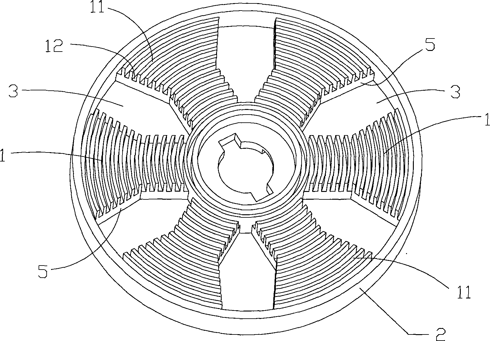
[0019] according to figure 1 and figure 2 As shown, it is the best embodiment of the present invention, the electromagnetic heating coil disk includes a coil disk support 2 with several winding parts 1, and the center of the winding part 1 layer is radially arranged on the coil disk support 2. The back side of the winding part 1 is provided with an accommodating groove, and a magnetic strip (not shown in the figure) is installed in the accommodating groove. A spacer cavity 3 is left between adjacent winding parts 1, such as figure 1 and image 3 As shown, the spacer cavity 3 can facilitate the heat dissipation of the enameled wire 4, and the wire slots 12 on the winding part 1 form a concentric circle structure together. The winding part 1 is provided with a number of baffles 11, and the baffles 11 are arc-shaped structures. Wire slots 12 are formed between adjacent baffle plates 11, and stoppers 6 are also arranged on the baffle plate 11, such as figure 2 As shown, duri...

Embodiment 2

[0023] see Figure 4 As shown, the structure of this embodiment is basically the same as that of Embodiment 1, the only difference is: the enameled wire 4 of this embodiment is a single-layer structure, and at the same time, the changing positions of the enameled wire 4 of this embodiment are not concentrated in the same interval cavity 3. Instead, the variable winding between adjacent wire slots 12 is carried out on any interval cavity 3 at will. The enameled wire 4 is arranged in the same way on the winding part 1. Its winding method is as follows:

[0024] The first circle is wound first, and then the second circle is wound through one of the spacer cavities 3, and then the third circle is wound through another spacer cavity 3, and the fourth circle, the fifth circle..., According to this method, the electromagnetic heating coil disc described in the cost embodiment is wound.

[0025] Embodiments of the present invention include but are not limited to the above two embodim...


PUM


Abstract

The invention discloses an electromagnetic heating coil plate, comprising a coil plate bracket provided with a plurality of coiling parts. A magnetic bar is arranged on the back surface of each coiling part; an interval cavity is reserved between the adjacent coiling parts; a plurality of baffle plates are arranged on the coiling parts; a coil groove is formed between the adjacent baffle plates; the coil grooves on the coiling parts commonly form a concentric circle structure; and a varnished wire is coiled on each coil groove and coils from one circle of the coil groove to the adjacent circle of the coil groove in any internal cavity. Accordingly, the coiling parts on the coil plate bracket can be arranged in a consistent structure, so as to greatly simplify the structure of the coil plate bracket and a structure of a preparation die. When a producer coils, the random coiling from one circle of the coil groove to the adjacent circle of the coil groove is realized in any one of the interval cavities between the coiling parts. The electromagnetic heating coil plate is flexible and convenient.

Description

technical field [0001] The invention relates to the technical field of a heating coil disk for an electromagnetic oven, in particular to an electromagnetic heating coil disk. Background technique [0002] In the existing electromagnetic cooker products on the market, there is a heating coil disk with double-layer enameled wire wound on the concentric wire slot on the coil disk support, forming a double-layer sparse winding structure, which can improve the electromagnetic heating effect and effectively reduce the overall volume , so it is favored by induction cooker producers. The heating coil disk of this structure, such as the structure described in the Chinese utility model patent CN201536437U, appears in the majority. A magnetic strip is set on the back of the jumper part, and the enameled wire realizes the jumper at the jumper part. [0003] However, the structure disclosed in the above-mentioned patent is fixed in the hollow position in the middle of the wire jumper t...

Claims


Application Information

Patent Timeline
Patent Type & Authority Applications(China)
IPC IPC(8): H05B6/36
Inventor 李军艳
Owner 佛山市心静电磁科技有限公司
Why Eureka
Try Eureka