Centralized display system of indicator lamps

A centralized display and indicator light technology, applied in the direction of electric lamp circuit layout, lighting devices, light sources, etc., can solve the problems of inability to adjust arbitrarily, difficulty in installation and connection, and many cables, and achieve easy processing and production, and human-computer interaction Friendly, strong overall effect

Inactive Publication Date: 2012-07-11
BEIJING DATANG GOHIGH DATA NETWORKS TECH CO LTD
View PDF4 Cites 4 Cited by
  • Summary
  • Abstract
  • Description
  • Claims
  • Application Information

AI Technical Summary

Problems solved by technology

[0006] 3. For some business cards, due to their high density, the allowable panel strip size is relatively small. Therefore, for these business cards, LED indicators are not easy to install;
[0007] 4. This distributed display method of LED indicator lights cannot be well applied to occasions that require centralized display of system status;
[0008] 5. The position of the LED indicator is restricted by the position of the board and cannot be adjusted arbitrarily
[0010] 1. It is a troublesome thing to directly install many LED indicator lights (dozens to hundreds) on the metal panel of the chassis one by one, and the labor cost is relatively high;
[0011] 2. Make a PCB display board, install all LED indicators on it, and then paste the PCB display board with LED indicators on the inside of the chassis panel. This is a specific implementation method of centralized display of LED indicators , however, for this implementation method, how to ensure the installation accuracy of the LED indicator light and how to solve the problem of manufacturability are difficult problems;
[0012] 3. There are too many cables from each service card to the panel on which all LED indicators are installed, making installation and connection difficult and costly

Method used


Image

  • Centralized display system of indicator lamps
  • Centralized display system of indicator lamps

Examples


Embodiment Construction

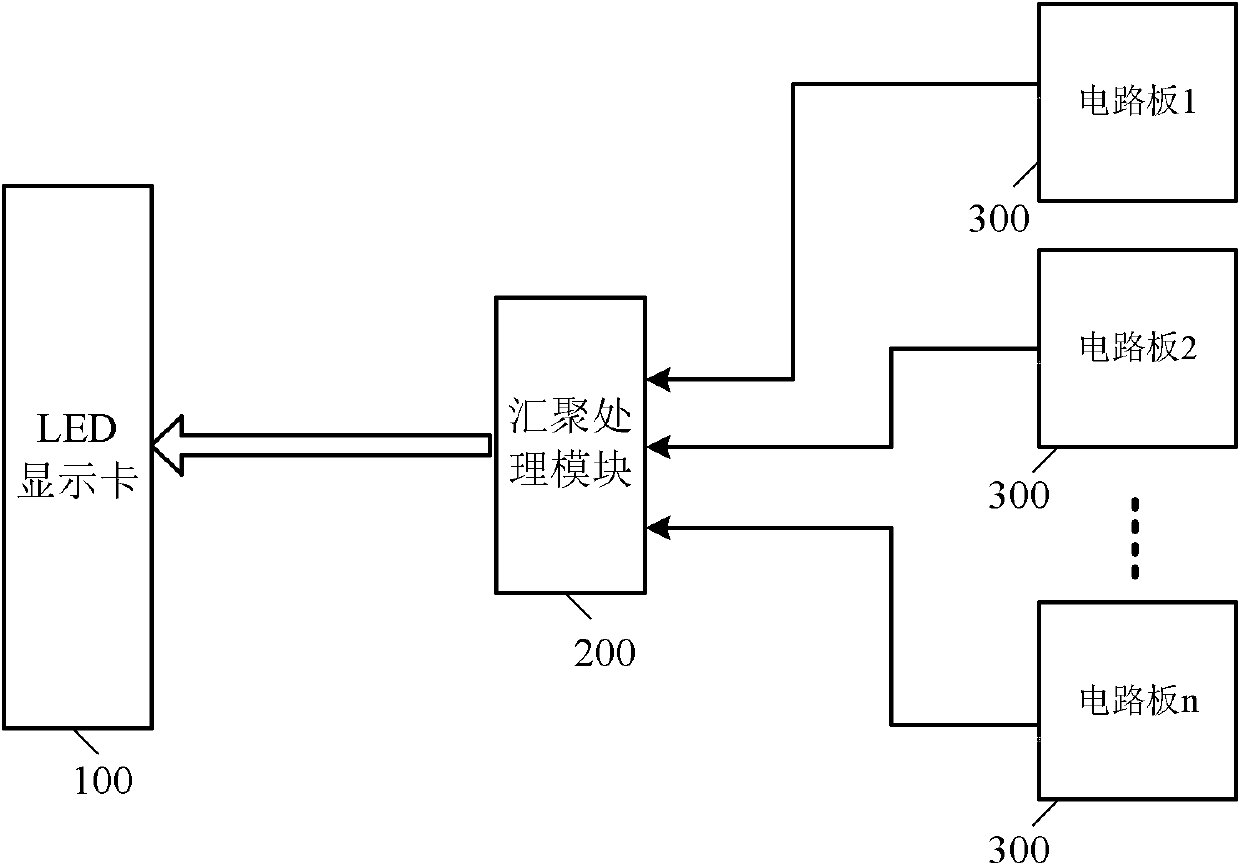
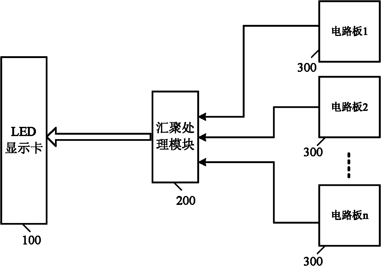
[0021] Such as figure 1 As shown, the centralized indicator light display system of the present invention includes a convergence processing module 200 and an LED display card 100. The convergence processing module 200 is connected to the LED display card 100 through a serial data cable. The convergence processing module 200 collects the LED states of each circuit board 300 signal, convert all LED state signals into serial data in a set serial format and send it to the LED display card 100 through the serial data cable, and the LED display card 100 converts the received serial data into predetermined parallel format After the parallel data, the corresponding LED indicators on the LED display card 100 are driven to display. In practical applications, the data formats of the LED state signals of each circuit board 300 may be the same or different, and the change rates of the LED state signals of each circuit board 300 may be the same or different.

[0022] The LED display card 1...


PUM


Abstract

The invention discloses a centralized display system of indicator lamps, which comprises a gathering and processing module and a light-emitting diode (LED) display card, wherein the gathering and processing module acquires the LED state signals of all circuit boards, converts all the LED state signals into serial data in set serial formats, and sends the data to the LED display card; and the LED display card converts the received serial data into parallel data in preset parallel formats, and drives corresponding LED indicator lamps on the LED display card to indicate. According to the system, the states of the LED indicator lamps of the equipment can be displayed in a centralized way, so that the overall feeling is strong, and man-machine interaction is friendly. The centralized display system of the indicator lamps is particularly applicable to communication equipment with high-density access cables.

Description

technical field [0001] The invention relates to a system for centralized display of indicator lights. Background technique [0002] In communication equipment, LED indicators are often required to display the status of the device system and the status of each access port, such as the power status of the device, the connection status of the network port, the running status of the software, the speed of the Ethernet port, and whether there is Ethernet packet sending and receiving, etc. LED indicators are required to display. For small devices, since the number of LED indicator lights is small, the display of the LED indicator lights will not pose a difficulty. However, with the increase of equipment scale and capacity, especially equipment with a large number of line accesses, the display of LED indicators has become a problem worthy of attention. [0003] The current large-capacity communication equipment has a multi-card and backplane structure, and usually adopts a distri...

Claims


Application Information

Patent Timeline
IPC IPC(8): H05B37/02
Inventor 丛远建王彦珍
Owner BEIJING DATANG GOHIGH DATA NETWORKS TECH CO LTD
Why Eureka
Try Eureka