Eye protection desk lamp with light-emitting diode (LED) light source
A technology of LED light source and light source, which is applied in the direction of light source, electric light source, electric lamp circuit layout, etc., can solve the problems of inconspicuous protection of human eye health, consideration of human health from the perspective of photobiology, etc., and achieve novel structure and benefit to health , the effect of promoting metabolic function
- Summary
- Abstract
- Description
- Claims
- Application Information
AI Technical Summary
Problems solved by technology
Method used
Image
Examples
Embodiment 1
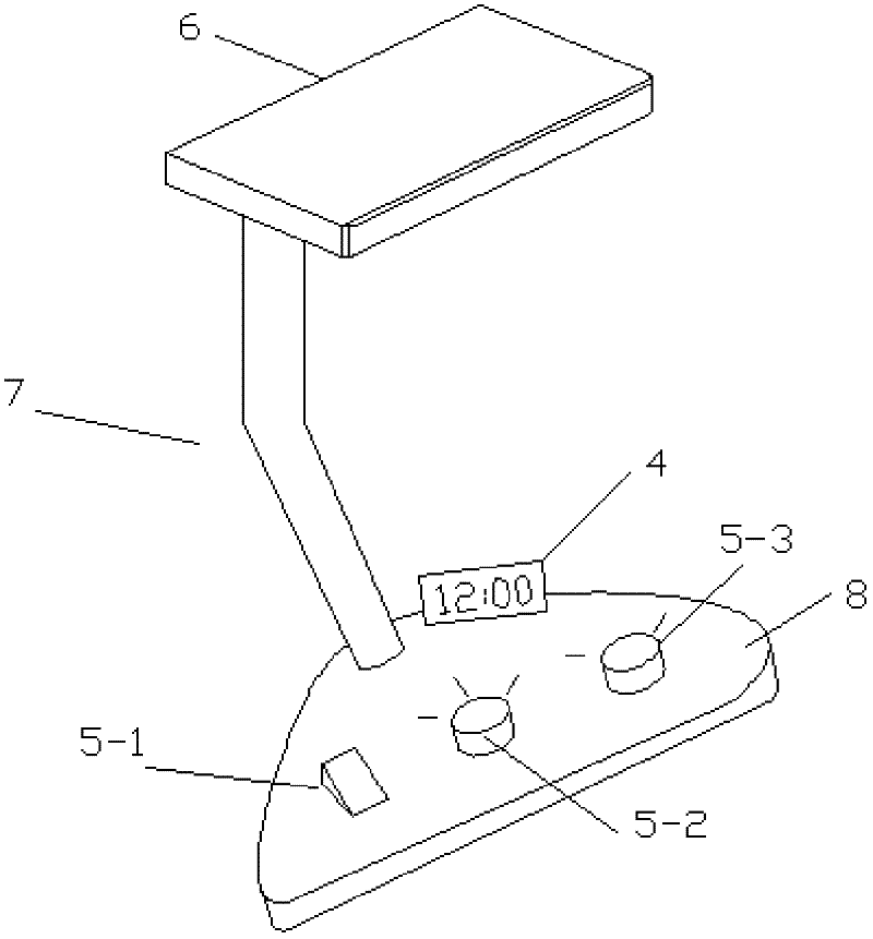
[0038] Embodiment 1: a kind of eye protection desk lamp that adopts LED light source, as figure 1 and figure 2 As shown, it includes a base 8, a lampshade 6, a connector 7 between the two ends of the base 8 and the lampshade 6, and a regulator 5, and also includes a luminous body 1 arranged in the lampshade 6, and a driving power source electrically connected to the luminous body 1. 2, and a control device 3 for controlling the driving power. Wherein the driving power supply 2 and the control device 3 can be in the base 8 , the connecting body 7 or the lampshade 6 , and the regulator 5 is installed on the base 8 .
[0039] The illuminant 1 is an LED combination light source, at least including a first sub-light source and a second sub-light source, the C / P value of the light emitted by the first sub-light source is greater than 2.5, and the C / P value of the light emitted by the second sub-light source is less than 2.5. The control device 3 outputs at least two kinds of sign...
Embodiment 2
[0045] Embodiment 2: An eye-protecting desk lamp using an LED light source, the LED illuminant 1 further includes a third sub-light source, and the third sub-light source is a red light source with a peak emission wavelength of 660nm-690nm.
[0046] Specifically, the first sub-light source and the second sub-light source are white LEDs, and the third sub-light source has a C / P value of zero and an emission wavelength of 670 nm is preferred. In order to achieve the C / P value required by the combined light source to imitate the natural light effect, the C / P value of the first sub-light source and the second sub-light source must be relatively high, that is, the relative spectral power (intensity) within the range of 400nm to 520nm higher; the other is relatively low (or even zero).
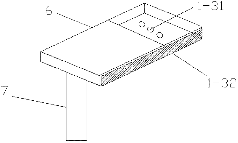
[0047] Such as image 3 As shown, the lampshade 6 is a light-transmitting surface at least on the front side and the bottom surface, and the third sub-light source includes two light emitting modul...
Embodiment 3
[0048] Embodiment 3: as Figure 4 As shown, the adjuster 5 disposed on the base 8 includes a switch button 5-1, a mode selection switch 5-2 and / or a third sub-light source adjustment switch 5-3. The switch button 5-1, the mode selection switch 5-2 and the third sub-light source adjustment switch 5-3 are all electrically connected with the control device 3 .
[0049] The control device 3 converts the control signal input by the manual control mode selection switch 5-2 or the third sub-light source adjustment switch 5-3 into a pulse width modulation signal and outputs it to the drive power supply 2 through the pulse width modulation method, and converts the C / P value and the intensity of light are converted into the electrical signal duty ratio output corresponding to the corresponding sub-light source; the driving power supply 2 controls the light intensity of the corresponding sub-light source according to the input duty ratio signal, and then controls the C of the correspondi...
PUM
 Abstract
Description
Claims
Application Information
 - R&D
- Intellectual Property
- Life Sciences
- Materials
- Tech Scout
- Unparalleled Data Quality
- Higher Quality Content
- 60% Fewer Hallucinations
Browse by: Latest US Patents, China's latest patents, Technical Efficacy Thesaurus, Application Domain, Technology Topic, Popular Technical Reports.
© 2025 PatSnap. All rights reserved.Legal|Privacy policy|Modern Slavery Act Transparency Statement|Sitemap|About US| Contact US: help@patsnap.com


