Dust remover

A dust collector, dust and gas separation technology, applied in chemical instruments and methods, dispersed particle separation, combined devices, etc., can solve the problems of increasing energy consumption and operating costs, increasing equipment investment and floor space, etc., to achieve a combined structure Simple and easy, manufacturing and installation costs and low footprint, consumable savings

Active Publication Date: 2012-07-18
FOSHAN HUMAN HABITAT ENVIRONMENTAL PROTECTION ENG
View PDF7 Cites 5 Cited by
  • Summary
  • Abstract
  • Description
  • Claims
  • Application Information

AI Technical Summary

Problems solved by technology

However, this not only needs to increase equipment investment and floor space, but also increases energy consumption and operating costs

Method used


Image

  • Dust remover
  • Dust remover
  • Dust remover

Examples


Embodiment 1

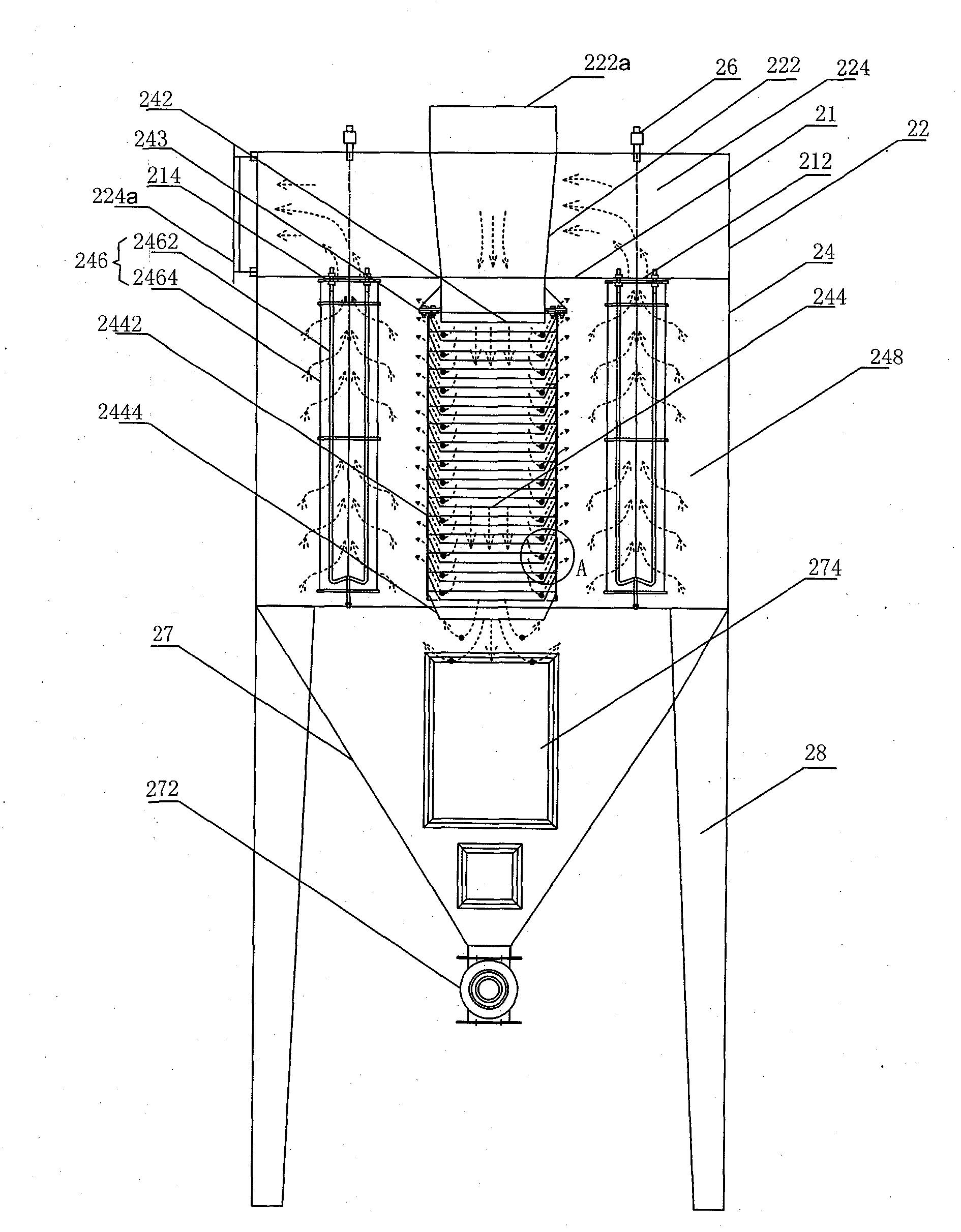
[0024] see figure 2 , which is a structural schematic diagram of the bag filter of the present invention. The bag filter 20 includes a dust removal device 26 , an upper box 22 , a middle box 24 , an ash hopper 27 and supporting feet 28 from top to bottom.

[0025] The upper box body 22 is a closed space, including an exhaust gas intake passage 222 and a clean air chamber 224 . The exhaust gas inlet channel 222 is a closed channel arranged in the middle of the upper box body 22 and runs through its upper and lower ends, and the upper part of the exhaust gas inlet channel 222 is an exhaust gas inlet 222a. The space in the upper case 22 except for the exhaust gas intake passage 222 is a clean air chamber 224 . A side wall of the clean air chamber 224 of the upper case 22 has a clean air outlet 224a.

[0026] The middle box 24 is arranged below the upper box 22, and forms a closed space with the ash hopper 27 below it. The middle box 24 includes an exhaust gas inlet 242 , a d...

Embodiment 2

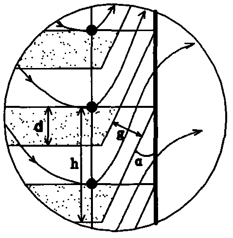
[0040] This embodiment is substantially the same as Embodiment 1, and the only difference is that the vertical height h between the upper and lower end openings of the platform formed by the blades is 120 mm, and the angle α between the blades 2444 and the bracket 2442 is 25°, correspondingly The vertical height d of the overlapping portion between two adjacent blades is 40mm, and the gap g between the overlapping portions of two adjacent blades is 33.8mm. The number of leaves is 16. The number of fixed brackets is 3. The waste gas inlet 242 is directly inserted into the dust and gas separation device 244, and the vertical height of the overlapping part of the blade of the dust and gas separation device is 40mm.

Embodiment 3

[0042] This embodiment is substantially the same as Embodiment 1, the only difference being that the height h between the upper and lower end openings of the platform formed by the blades is 180 mm, the angle α between the blades 2444 and the bracket 2442 is 45°, adjacent The vertical height d of the overlapping portion between the two blades is 60 mm, and the gap g between the overlapping portions of two adjacent blades is 85 mm. The number of leaves is 11. The number of brackets is 4. The exhaust gas inlet 242 is directly inserted into the dust and gas separation device 244, and the vertical height of the overlapping part of the blade of the dust and gas separation device is 60 mm.


PUM

PropertyMeasurementUnit
heightaaaaaaaaaa
heightaaaaaaaaaa
heightaaaaaaaaaa

Abstract

The invention relates to a dust remover, which comprises an upper tank body and a middle tank body. The upper tank body comprises a waste gas inlet channel and a gas purification chamber, wherein the waste gas inlet channel is a sealed channel, and a waste gas inlet is arranged at the upper portion of the waste gas inlet channel. The space in the upper tank body except the waste gas inlet channel is treated as the gas purification chamber, and a purification gas outlet is positioned on the lateral wall of the of the gas purification chamber. The middle tank body is positioned below the upper tank body and comprises a waste gas inlet, a dust-gas separation device, a filter device and a filter chamber, wherein the waste gas inlet is positioned at the upper end of the dust-gas separation device and connected with the lower portion of the waste gas inlet channel, the dust-gas separation device is vertically arranged in the middle tank body and penetrates through the upper end and the lower end of the middle tank body to form a dust-gas separation channel, the filter device is arranged on the lateral side of the dust-gas separation device, an opening of the filter device is communicated with the gas purification chamber of the upper tank body, and the space in the middle tank body except the waste gas inlet, the dust-gas separation device and the filter device is treated as a filter chamber. The dust remover is efficient, can save energy, protects material consumption, prolongs service life and is low in daily running cost.

Description

technical field [0001] The invention belongs to the field of environmental protection dust removal equipment, and in particular relates to a dust collector. Background technique [0002] see figure 1 , which is a schematic structural diagram of a traditional bag filter. The bag filter includes a dust removal device 11 , an upper box 12 , a middle box 13 , an ash hopper 14 and supporting feet 15 from top to bottom. [0003] The upper box 12 is a closed space as a clean air chamber, and its side wall is provided with a clean air outlet 121. The upper box 12 and the middle box 13 are separated by a flower plate 122, which is provided with Flower holes 123 are arranged for ventilation. [0004] The middle box body 13 and the ash hopper 14 below it form a closed space. The middle box 13 includes an exhaust gas inlet 131 , a guide baffle 132 , a filter device 133 and a filter chamber 134 . The exhaust gas inlet 131 is disposed on a side wall of the middle box 13 . The guide ...

Claims


Application Information

Patent Timeline
Patent Type & Authority Applications(China)
IPC IPC(8): B01D50/00
Inventor 黄清豹
Owner FOSHAN HUMAN HABITAT ENVIRONMENTAL PROTECTION ENG
Why Eureka
Try Eureka