Hydraulic power fixture of numerical-control machine tool

A hydraulic power, CNC machine tool technology, applied in the direction of clamping, manufacturing tools, metal processing machinery parts, etc., can solve the problems of difficult to ensure the consistency of parts processing accuracy, long auxiliary parts processing time, low production efficiency, etc., to achieve Novel fixture structure, shortening auxiliary time and improving work efficiency

Inactive Publication Date: 2012-07-18
NANJING INST OF TECH
View PDF6 Cites 6 Cited by
  • Summary
  • Abstract
  • Description
  • Claims
  • Application Information

AI Technical Summary

Problems solved by technology

However, for some shell parts, since they are non-revolving parts, the hole processing cannot be achieved with a general-purpose self-centering clamping mechanism.
The traditional method is to use the process method of sub-process processing. Multiple processing equipment will be used to complete the processing of one part. Therefore, the labor intensity is high, the auxiliary time of part processing is long, and the production efficiency is low.
More importantly, with the manual clamping method, it is not easy to guarantee the machining accuracy of the parts and the consistency of the parts size, and it is easy to produce waste products and unqualified parts

Method used


Image

  • Hydraulic power fixture of numerical-control machine tool
  • Hydraulic power fixture of numerical-control machine tool
  • Hydraulic power fixture of numerical-control machine tool

Examples


Embodiment Construction

[0019] The present invention will be further described below in conjunction with the accompanying drawings.

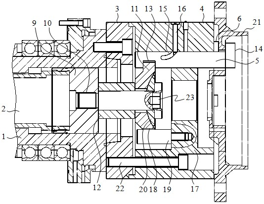
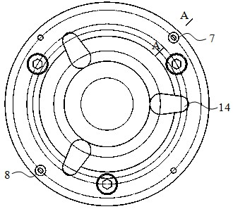
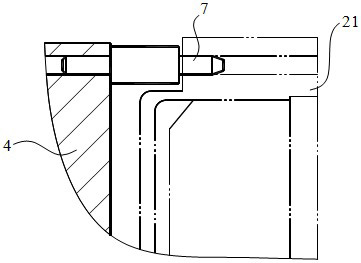
[0020] combine figure 1 , image 3 As shown, a hydraulic power clamp for a CNC machine tool of the present invention includes: an oil cylinder and a pull rod 2 located in the inner cavity of the main shaft 1, a transition plate 3 is installed on the front end of the main shaft 1, and is fastened by six screws, and the clamp body 4 is installed on the front end of the main shaft 1. The front end of the transition plate 3 is fastened by six screws 22 . Three claw shafts 5 are distributed on the inner wall of the clamp body 4 , and three steel bases 6 , two circular positioning pins 7 and two diamond-shaped positioning pins 8 are arranged at the front end of the clamp body 4 . The front end of the pull rod 2 is provided with a threaded sleeve 9, which is provided with a bolt 10 protruding to the front end, and the front end of the bolt 10 is connected with the pressure ...


PUM


Abstract

The invention discloses a hydraulic power fixture of a numerical-control machine tool, which belongs to the field of machining and comprises an oil cylinder, a draw bar, a transitional plate and a fixture body. A pressure plate and a pressure claw shaft are arranged in an inner cavity of the fixture body, the pressure claw shaft is meshed with the outer edge of the pressure plate, a guiding groove is disposed on the pressure claw shaft, and the pressure claw shaft peripherally swings while moving axially under effects of the guiding groove and a guiding screw. The hydraulic power fixture is novel in structure, and firmly and stably clamps a shell part effectively, machining precision can be effectively guaranteed, machining auxiliary time of the part is shortened, and work efficiency is improved. In addition, the hydraulic power fixture can clamp different parts by means of adjusting the structure of the pressure claw shaft and the size of a pressure head, and accordingly is wide in applicability.

Description

technical field [0001] The invention relates to the field of numerical control machine tool equipment, in particular to a hydraulic power clamp of a numerical control machine tool used for processing shell parts. Background technique [0002] In the machinery manufacturing industry, CNC machine tools, especially CNC lathes, are widely used to process disc and shaft parts. During the processing of conventional rotary parts, many parts need to use the end face and inner hole as the positioning clamping surface for cutting the outer circle, end face, thread and axial cutting. This kind of parts processing, especially the outer circle, end face And threads, etc. There are many traditional clamping and positioning mechanisms to meet the requirements of use. And for some shell parts, because the hole processing of non-revolving body parts, it cannot be realized with a general self-centering clamping mechanism. The traditional method is to use the process method of sub-process pr...

Claims


Application Information

Patent Timeline
Patent Type & Authority Applications(China)
IPC IPC(8): B23Q3/12
Inventor 刘桂芝杨文亮李小笠郁汉琪冯虎徐有峰史建俊
Owner NANJING INST OF TECH
Why Eureka
Try Eureka