Platen moving pair for full-automatic printing machine

A technology of printing machine and moving pair, applied in the field of moving pair of automatic printing machine platen, can solve the problem that the horizontal direction adjustment mechanism cannot smoothly transfer the printing platen, and the vertical feeding mechanism cannot be fully adjusted, structural reliability and stability. problems such as major problems, to achieve the effect of improving printing efficiency, improving reliability and stability, and prolonging drying time

Active Publication Date: 2012-07-18
如皋市天元服饰印业有限公司
View PDF6 Cites 10 Cited by
  • Summary
  • Abstract
  • Description
  • Claims
  • Application Information

AI Technical Summary

Problems solved by technology

Although the new printing machine with the above-mentioned structure increases the number of platens per unit area and improves the output, it still has certain problems: the two sets of vertical feeding mechanisms on the three-dimensional feeding and discharging frame adopt a chain structure, and the chain drives When printing the platen, the two sets of vertical feeding mechanisms cannot be completely synchronized. After accumulating errors, the heights of the printing platens of the vertical feeding mechanisms at both ends of the horizontal adjustment mechanism are not at the same level, resulting in the inability of the horizontal adjustment mechanism to hand over the printing table smoothly. board, so there are big problems in the reliability and stability of the above structure

Method used


Image

  • Platen moving pair for full-automatic printing machine
  • Platen moving pair for full-automatic printing machine
  • Platen moving pair for full-automatic printing machine

Examples


Embodiment Construction

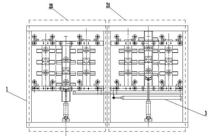
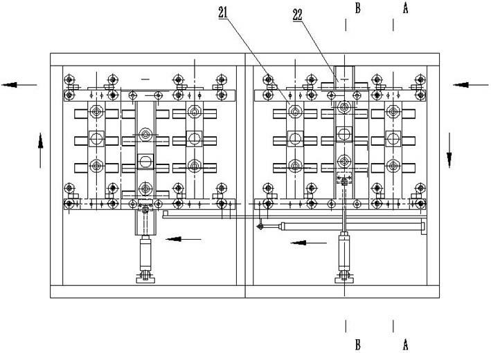
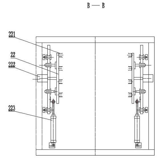
[0022] Such as figure 1 , 2 , 3, and 4, including the frame 1, the feeding side lifting and conveying mechanism 2A, the discharging side lifting and conveying mechanism 2B, the horizontal conveying mechanism 3, the lifting and supporting bracket 21, the platen support Ⅰ211, and the clamping drive mechanism Ⅰ212 , Lifting transfer bracket 22 , platen support II 221 , clamping drive mechanism II 22 , transfer drive mechanism 223 .

[0023] The above-mentioned frame 1 is equipped with a side-by-side lifting and conveying mechanism 2A on the feeding side and a lifting and conveying mechanism 2B on the discharging side, and a horizontal conveying mechanism for its cohesive function is set between the lifting and conveying mechanism 2A on the feeding side and the lifting and conveying mechanism 2B on the discharging side. Mechanism 3, the horizontal conveying mechanism 3 is used to transfer the printing table 4 between the lifting conveying mechanism 2A on the feeding side and the ...


PUM


Abstract

The invention relates to a platen moving pair for a full-automatic printing machine. The platen moving pair comprises a rack, and a feeding side lifting conveying mechanism, a discharge side lifting conveying mechanism, and a horizontal conveying mechanism, which are installed on the rack. The platen moving pair is characterized in that each of the feeding side lifting conveying mechanism and thedischarge side lifting conveying mechanism comprises a lifting support bracket and a lifting handover bracket, platen supports are distributed on the lifting support brackets and the lifting handoverbrackets, clamping driving mechanisms are arranged on the lifting support brackets and the lifting handover brackets and handover driving mechanisms are arranged on the lifting handover brackets. Through arrangement of the lifting conveying mechanisms in such a structure form, the quantity of printing platens is increased in unit space on the basis that the floor space of the printing machine is not increased and the printing efficiency is improved for sure. By virtue of clamping and releasing actions of the lifting support brackets and the lifting handover brackets and in cooperation with the lifting handover brackets, the printing platens can be handed over successfully and operation reliability and stability of equipment is ensured.

Description

technical field [0001] The invention relates to a printing machine, in particular to a platen moving pair of a fully automatic printing machine. Background technique [0002] As far as the current home and abroad are concerned: printing machines are mainly divided into rotary screen printing machines and flat screen printing machines according to printing plates. The printing plate of the rotary screen printing machine is a cylinder, and the rotary screen printing machine directly uses a guide belt. The printing speed is relatively fast, up to 5000m per hour, but the disadvantage is that it can only print fixed patterns, which is suitable for mass production of gray fabrics , the scope of use is narrow. The printing plate of the flat screen printing machine is a flat screen plate, and the feeding cloth of the flat screen printing machine has both a guide belt and a platen. Among them, the platen flat screen printing machine is called a circular or oval printing machine, wh...

Claims


Application Information

Patent Timeline
Patent Type & Authority Applications(China)
IPC IPC(8): B41F15/14
Inventor 邱德强
Owner 如皋市天元服饰印业有限公司
Why Eureka
Try Eureka