Speed-reducing type wheel electric drive system of electric vehicle

An electric drive system, electric vehicle technology, applied in motion deposition, power plant, vehicle components, etc., can solve the problems of limited vibration reduction, narrow space, and high system cost, reduce unsprung mass, and reduce negative mass effects. Effect

Active Publication Date: 2012-07-18
WUXI YONGKAIDA GEAR
View PDF5 Cites 5 Cited by
  • Summary
  • Abstract
  • Description
  • Claims
  • Application Information

AI Technical Summary

Problems solved by technology

However, the cost of the former system is relatively high, while the latter can only use a dynamic shock absorber with a small mass due to the small space inside the rim, and its damping effect is limited.

Method used


Image

  • Speed-reducing type wheel electric drive system of electric vehicle
  • Speed-reducing type wheel electric drive system of electric vehicle
  • Speed-reducing type wheel electric drive system of electric vehicle

Examples


Embodiment Construction

[0012] The specific implementation manner of the present invention will be described below in conjunction with the accompanying drawings.

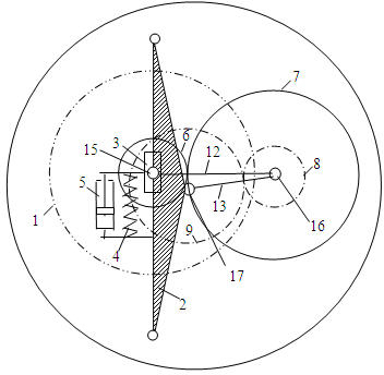
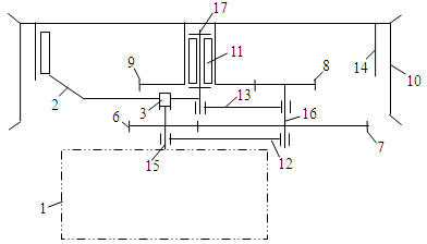
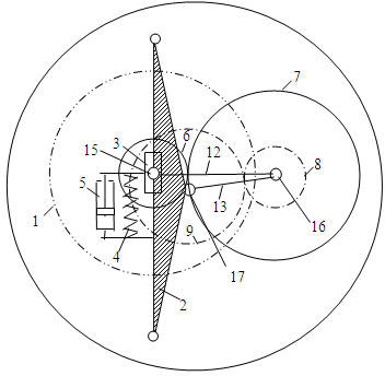
[0013] Such as figure 1 , figure 2 As shown, the first-stage reduction gear pair consists of a first-stage driving gear 6 fixedly connected to the output shaft of the motor shaft 15 and a first-stage driven gear 7 fixedly connected to the intermediate shaft 16; The secondary driving gear 8 of 16 and the secondary driven gear 9 fixedly connected to the hub 10 are formed; the hub 10 is fixedly connected with the secondary driven gear 9 coaxially, and is supported on the suspension steering knuckle 2 through the hub bearing 11 on the wheel support shaft 17, and rotate around the axis of the wheel support shaft 17.

[0014] The two ends of the primary reduction gear pair center connecting rod 12 are respectively hinged with the motor shaft 15 and the intermediate shaft 16 through a rotary pair, and the axis of the rotary pair coincides with...


PUM


Abstract

The invention discloses a speed-reducing type wheel electric drive system of an electric vehicle. A hub is supported on a wheel support shaft on a suspension steering knuckle through a hub bearing; a first-level speed reducing gear pair is in transmission with a second-level speed reducing gear pair; a motor shaft of a wheel drive motor is in pivot joint with a slider of a sliding guide pair; a guide rail of the sliding guide pair is vertically fixed on the suspension steering knuckle; the wheel drive motor can relatively slide on the suspension steering knuckle in the vertical direction; and the slider and the suspension steering knuckle are borne by a dynamic vibration reducing spring and a dynamic vibration reducing damper. According to the invention, through the movable connection design between a drive motor and a speed reducing transmission mechanism, the dead weight of the drive motor is transformed into the mass of a dynamic vibration reducer, and thus the vibration reducing function of the dynamic vibration reducer can be realized without needing additional mass block of the dynamic vibration reducer. Through the invention, the unsprung mass of the wheel electric drive system is effectively reduced, and the dead weight of the drive motor generates an effect of reducing the negative effect of the unsprung mass of the wheel electric drive system.

Description

technical field [0001] The invention relates to the field of electric vehicle chassis and transmission technology, in particular to a deceleration wheel-side electric drive system of an electric vehicle that utilizes the self-weight of a driving motor to realize a vibration reduction function. Background technique [0002] The wheel-side electric drive system of an electric vehicle refers to the driving form in which the drive motor is arranged in or near the drive wheel, and the power is directly transmitted to the wheel by the motor or through a reduction device to drive the vehicle. Because the wheel-side electric drive system omits the clutches, universal joints, transmission shafts and differentials of traditional cars, it has unique advantages compared with centralized motor drives: the vehicle has a simple structure and large available space; The chain is short and the transmission efficiency of the drive system is high; the torque of each drive wheel is independently...

Claims


Application Information

Patent Timeline
Patent Type & Authority Applications(China)
IPC IPC(8): B60K7/00
Inventor 荣兆明
Owner WUXI YONGKAIDA GEAR
Why Eureka
Try Eureka