
Fastener structure for adjusting track gauge

A technology for adjusting components and gauges, applied in tracks, fixed rails, roads, etc., can solve the problems of soft gauge pads, low toughness of product materials, and reduced product use effects, and achieve small gauge adjustment errors. Simple way to achieve overall effect

Inactive Publication Date: 2012-07-18
张海洋
View PDF7 Cites 8 Cited by
  • Summary
  • Abstract
  • Description
  • Claims
  • Application Information

AI Technical Summary

Problems solved by technology

[0003] (1) The compressive strength of the gauge pad is insufficient, and compression yielding phenomenon often occurs in field use
[0004] (2) The gauge pad has insufficient bending strength, and there are defects such as fracture, warping, and bending in field use
It is understood that all manufacturers of reinforced materials cannot meet this requirement, which is one of the reasons for the fracture of low-toughness materials and bending of high-toughness materials in products
[0006] (4) During the operation of the train, due to the huge pressure, frequent vibration and friction, a lot of heat is generated, which makes the gauge pad soft and greatly reduces the use effect of the product
[0008] (6) The adjustment accuracy is determined by the type and type of the gauge pad. The higher the required accuracy, the more types of gauge pads there are, which is not conducive to the maintenance and repair work in the operation process.

Method used


Image

  • Fastener structure for adjusting track gauge
  • Fastener structure for adjusting track gauge
  • Fastener structure for adjusting track gauge

Examples


Embodiment 1

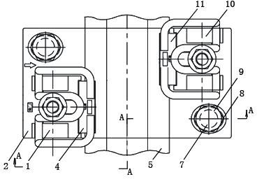
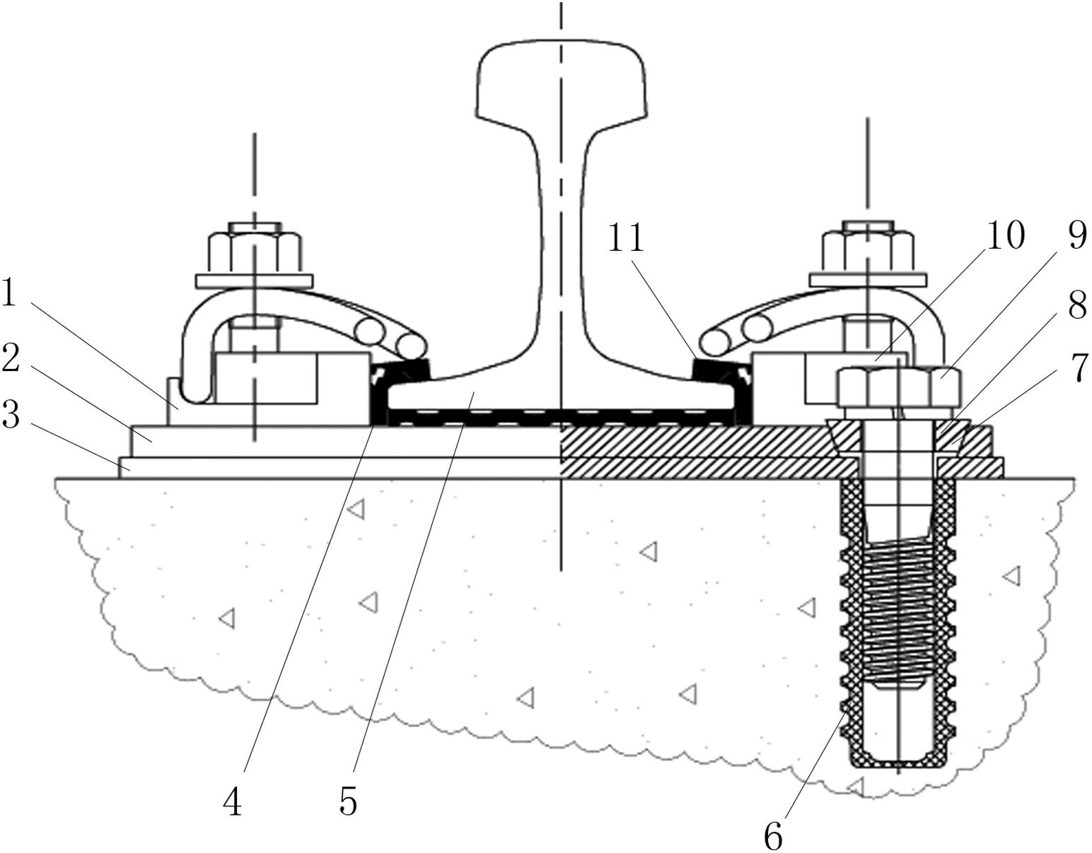
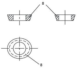
[0029] Such as figure 1 , figure 2 , image 3 , Figure 4 A fastener structure for adjusting the gauge is shown, which includes: an iron backing plate 2, a left iron seat 1 and a right iron seat 10 fixed on the iron backing plate 2, which are relatively arranged on both sides of the rail 5, and located on the iron backing plate 2. The left and right iron bases 1, 10 are buckled on the left L-shaped gauge pad 4 and the right L-shaped gauge pad 11 on the rail 5. The iron backing plate 2 is placed on the sleeper through the backing plate 3, and the left 1. The two L-shaped sides of the right L-shaped gauge pad 4 and 11 are of different thicknesses, and the two sides of the left L-shaped gauge pad 4 and the two sides of the right L-shaped gauge pad 11 have a difference in thickness between each two sides 1 to 3 mm, the adjacent matching positions of the left and right fasteners 1 and 10 are provided with adjustment components 7; the adjustment components 7 are composed of gaug...


PUM


Abstract

The invention discloses a fastener structure for adjusting a track gauge. The fastener structure comprises an iron base plate, a left iron seat and a right iron seat which are relatively arranged on two sides of a steel rail and fixed on the iron base plate and a left L-shaped track gauge pad and a right L-shaped track gauge pad which are arranged on the inner sides of the left iron seat and the right iron seat and buckled and pressed on the steel rail, wherein the iron base plate is arranged on a sleeper through a base plate; the two edges of each of the left L-shaped track gauge pad and the right L-shaped track gauge pad have different thicknesses, and a thickness difference is 1 to 3 mm; adjustment components are arranged at adjacent matched positions of the left iron seat and the right iron seat; each of the adjustment components mainly comprises a track gauge positioning block and an anchoring bolt; each track gauge positioning block consists of a central through hole in the middle and an elliptical taper outside; the elliptical tapers are matched with elliptical tapered holes in the iron base plate; and the track gauge positioning blocks are fixedly connected to the sleeper through the anchoring bolts. The fastener structure is simple and rational, has high practicability and a good effect, and is favorable for popularization and application.

Description

technical field [0001] The invention relates to a fastener connecting a rail and a track bed, in particular to a fastener structure for gauge adjustment. Background technique [0002] China's urban rail transit, which began in the 1990s, is developing rapidly. It is reported that 36 cities in China have designed and planned urban rail transit, and plan to build 96 rail transit lines around 2015. In rail transit design, fasteners are the main components connecting rails and ballast beds. There are many types of rail transit fasteners, mainly composed of three parts: buckling parts, elastic backing plates and anchor connectors. The shape, type and material of the components that make up the fastener system are closely related to the system function, connection method, manufacturing difficulty, construction maintenance method and economic cost. The fastener system is distinguished in different ways, and there are many types, such as: according to the connection method with the...

Claims


Application Information

Patent Timeline
Patent Type & Authority Applications(China)
IPC IPC(8): E01B9/66
Inventor 张海洋
Owner 张海洋
Learn More