

Joint for track panel and manufacturing and installing method
A technology of end and section steel, applied in the direction of track, laying track, track maintenance, etc.
- Summary
- Abstract
- Description
- Claims
- Application Information
AI Technical Summary
Problems solved by technology
Method used
Image

Examples
Embodiment 1
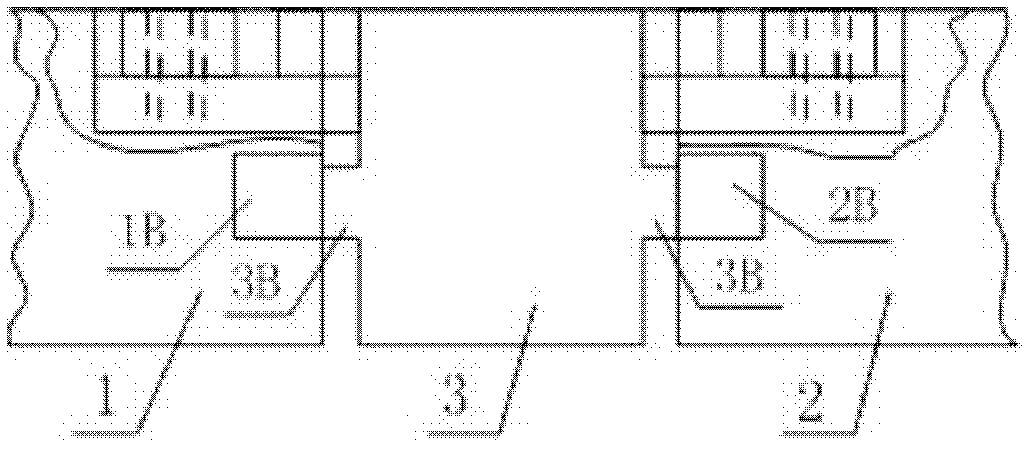
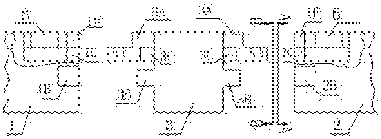
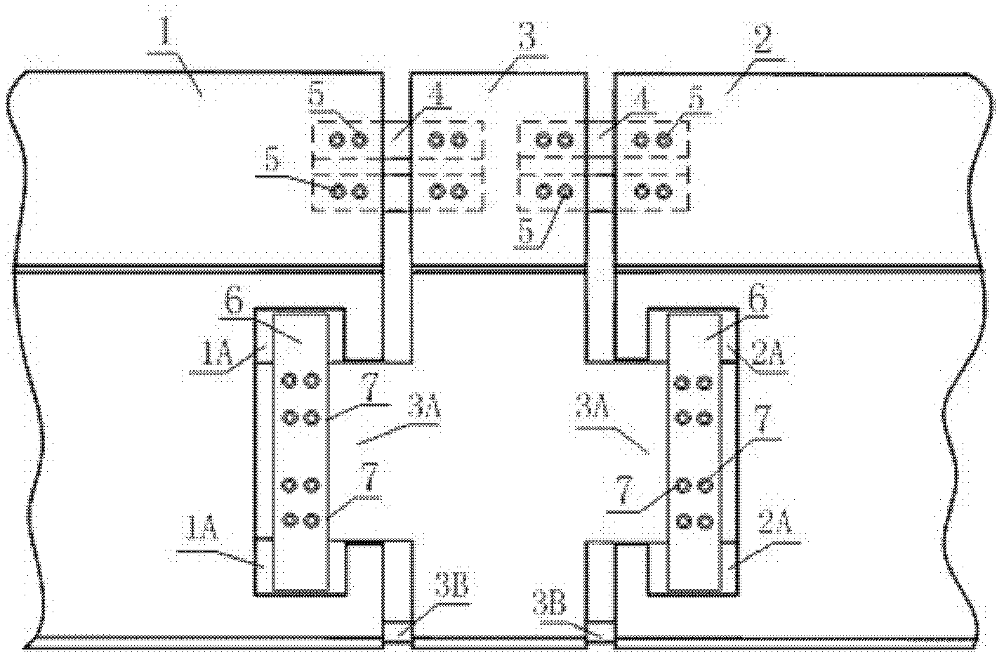
[0052] A rail row joint for medium and low-speed maglev trains, which consists of front F-shaped steel 1, rear F-shaped steel 2, middle F-shaped steel 3, single-key slider 4, slider bolt 5, and supporting slide plate 6. The front F-shaped steel 1 and the rear One end of the F-shaped steel 2 is processed into a mirror-symmetric groove structure, and the two ends of the middle F-shaped steel 3 are processed into a mirror-symmetrical convex plate structure. The processing ends of the front F-shaped steel 1, the middle F-shaped steel 3, and the rear F-shaped steel 2 are similar Correspondingly arranged in order from front to back, two pairs of corresponding wing plates are connected together by two connecting single-key sliders 4 and connecting slider bolts 5, and two pairs of corresponding wing plates are connected by two supporting sliders 6 and countersunk head bolts 7. The corresponding groove structure is connected with the convex structure to form an F-rail joint as a whole. ...
Embodiment 2
[0077] The front chute support plate 1A and the rear chute support plate 2A are as Figure 4 As shown, it is a pair of rectangular grooves with exactly the same size, which are located on the webs of the two opposite ends of the front F-shaped steel 1 and the rear F-shaped steel 2, and the distance from the ends of the front F-shaped steel 1 and the rear F-shaped steel 2 is equal to the front The width of baffle plate 1F and rear baffle plate 2F; Its depth is equal to the thickness of support slide plate 6; Its width is the width of support slide plate 6 plus 2 times of front and rear expansion and contraction; Its length is about the width in F-shaped steel web groove (see Figure 5 ), its main function is to make the supporting slide plate 6 slide back and forth in the groove after being connected with the web sliding plate 3A with the countersunk bolt 7 in the front chute support plate 1A and the rear chute support plate 2A, The sliding amount is equal to the designed expan...
Embodiment 3
[0093] The front chute support plate 1A and the rear chute support plate 2A are as Figure 4 As shown, it is a pair of rectangular grooves with exactly the same size, which are located on the webs of the two opposite ends of the front F-shaped steel 1 and the rear F-shaped steel 2, and the distance from the ends of the front F-shaped steel 1 and the rear F-shaped steel 2 is equal to the front The width of baffle plate 1F and rear baffle plate 2F; Its depth is equal to the thickness of support slide plate 6; Its width is the width of support slide plate 6 plus 2 times of front and rear expansion and contraction; Its length is about the width in F-shaped steel web groove (see Figure 5 ), its main function is to make the supporting slide plate 6 slide back and forth in the groove after being connected with the web sliding plate 3A with the countersunk bolt 7 in the front chute support plate 1A and the rear chute support plate 2A, The sliding amount is equal to the designed expan...
PUM
| Property | Measurement | Unit |
|---|---|---|
| Flexibility | aaaaa | aaaaa |
Abstract
Description
Claims
Application Information