Electro-hydraulic proportional relief valve

An electro-hydraulic proportional and overflow valve technology, which is applied in the direction of fluid pressure actuators, servo motor components, mechanical equipment, etc., can solve the problems of not being able to be 0, increase the input power, and limit the maximum value of the control pressure, etc., to achieve Reduce energy consumption, improve pressure control, and reduce heat generation

Inactive Publication Date: 2012-07-18
TAIYUAN UNIV OF TECH
View PDF10 Cites 6 Cited by
  • Summary
  • Abstract
  • Description
  • Claims
  • Application Information

AI Technical Summary

Problems solved by technology

[0003] There are two shortcomings in the above-mentioned existing control method and structure: one is to use a proportional electromagnet with unidirectional output capability to realize the conversion of electrical-mechanical signals, and the coil current cannot exceed the limit of the maximum operating temperature of the coil. If the current is too large, the maximum value of the control pressure will be limited under given conditions; the second is that the spring preload is used to press the pilot spool on the oil inlet when the output force of the electromagnet is 0, the spring The preloading force should be as small as possible, but not 0, so that the electro-hydraulic proportional relief valve has a minimum control pressure corresponding to the spring preloading force
[0004] In the prior art that solves the above-mentioned problems, the solution to the first problem is to increase the input power and increase the volume of the proportional electromagnet. The installation space is limited, and it will also be limited by the power supply
Another method is to adopt a more efficient heat dissipation technology to increase the maximum allowable current of the coil, which will greatly increase the complexity of the electro-hydraulic proportional relief valve
For the second problem, the body structure of the electro-hydraulic proportional relief valve is limited, and there is no good solution in itself. It can only be solved by changing its structural principle or using other methods in the hydraulic control system.

Method used


Image

  • Electro-hydraulic proportional relief valve
  • Electro-hydraulic proportional relief valve

Examples


Embodiment 1

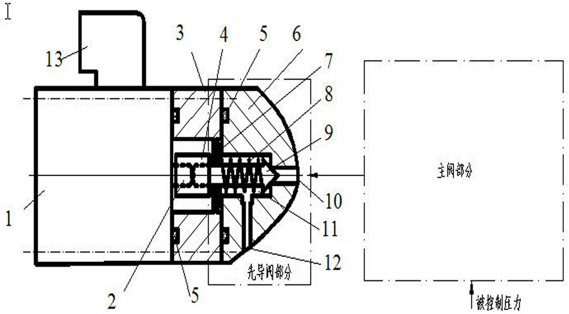
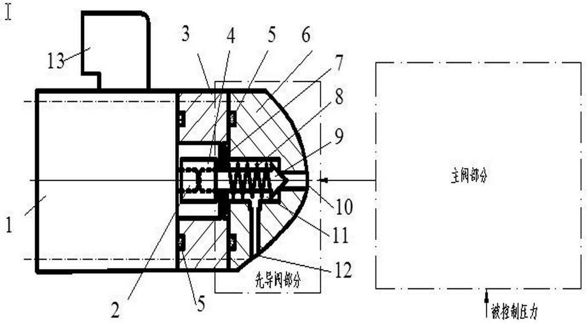
[0055] Such as figure 1 It is a structural schematic diagram of the electro-hydraulic proportional overflow valve designed according to the present invention. The electro-hydraulic proportional overflow valve includes a proportional electromagnet 1, a proportional electromagnet output rod 2, a connecting piece 4 and a spring 8.

[0056] The indicators of the designed electro-hydraulic proportional relief valve include: maximum overflow flow Q mm , pressure control range 0- P sm , according to the characteristics of the present invention, the preset control pressure of the designed electro-hydraulic proportional relief valve is given P s0 .

[0057] Utilize the present invention to design the electro-hydraulic proportional relief valve, in addition to designing according to the existing electro-hydraulic proportional relief valve, it is necessary to determine F k0 and the maximum allowable current of bidirectional proportional solenoid 1 I tm .

[0058] F k0 method ...


PUM


Abstract

An electro-hydraulic proportional relief valve is provided with a bidirectional proportional electromagnet. An output rod of the proportional electromagnet is axially rigidly connected with a pilot valve spool through a connector so as to drive the pilot valve spool bidirectionally. A spring of the electro-hydraulic proportional relief valve is compressed when no current is led into a coil of the bidirectional proportional electromagnet, the sum of the pretension force generated from the spring and the maximum output force of the proportional electromagnet in the same direction corresponds to the maximum control pressure controlled by the electro-hydraulic proportional relief valve, and the maximum control pressure is higher than control pressure generated when only thrust of the bidirectional proportional electromagnet acts individually. Accordingly, the maximum control pressure of the electro-hydraulic proportional relief valve is increased.

Description

technical field [0001] The invention relates to an electro-hydraulic proportional overflow valve, in particular to an electro-hydraulic proportional overflow valve used for electro-hydraulic proportional control in a hydraulic control system, which includes a pilot valve part and a main valve part. technical background [0002] In the hydraulic control system, especially the electro-hydraulic proportional control element, the function of the electro-hydraulic proportional overflow valve is to make the hydraulic oil pressure controlled by it proportional to the input voltage signal or current signal, and the electro-hydraulic proportional overflow valve The control circuit of the valve is connected to the proportional electromagnet coil installed inside the proportional electromagnet through the terminal. When a current flows through the coil, the output rod of the proportional electromagnet generates a unidirectional thrust, which produces a resultant force with the pressing ...

Claims


Application Information

Patent Timeline
Patent Type & Authority Applications(China)
IPC IPC(8): F15B13/02
Inventor 许小庆王旭平张婵爱
Owner TAIYUAN UNIV OF TECH
Why Eureka
Try Eureka