Gate mechanism

A movement and gate technology, which is applied to mechanical equipment, transmission parts, roads, etc., can solve the problem of small internal space of cylindrical rotating column swing gates, difficulty in meeting the layout requirements of cylindrical rotating column swing gates, It is inconvenient to route the electric control cables and other problems, so as to solve the wiring problem, reduce the size of the gate, and improve the matching accuracy

Inactive Publication Date: 2014-09-10
SHENZHEN JIESHUN SCI & TECH IND
View PDF6 Cites 0 Cited by
  • Summary
  • Abstract
  • Description
  • Claims
  • Application Information

AI Technical Summary

Problems solved by technology

[0002] Due to the small internal space of the cylindrical rotating column swing gate, it is difficult to meet the layout requirements of the cylindrical rotating column swing gate with the movement assembled by the existing general reducer and motor, and it is also inconvenient to route the electric control cables

Method used


Image

  • Gate mechanism
  • Gate mechanism
  • Gate mechanism

Examples


Embodiment Construction

[0020] Hereinafter, the present invention will be further described in detail through embodiments in combination with the drawings.

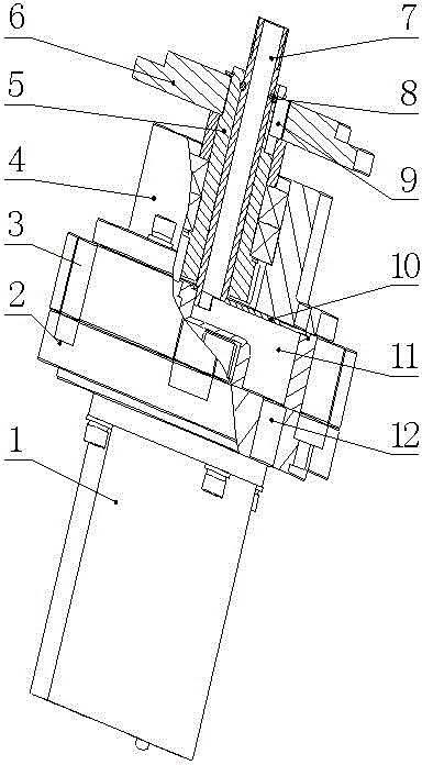
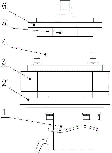
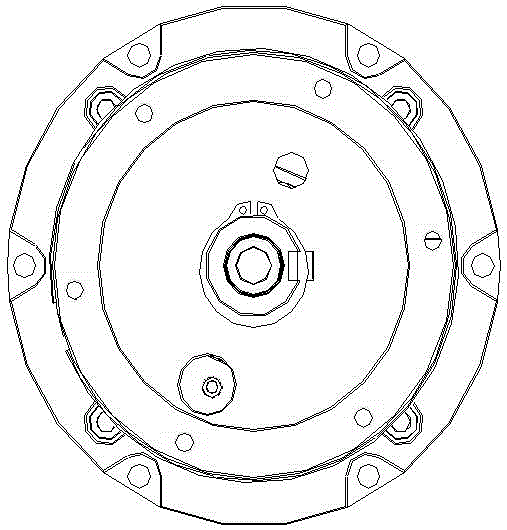
[0021] See figure 1 with image 3 The gate movement is, for example, a movement for channel gates. In one embodiment, the movement includes a motor 1, a reducer, and an output flange 6. The reducer includes a cylindrical reducer housing, internal gears and connections. The output gear shaft assembly 5 of the output flange is arranged concentrically with the reducer case.

[0022] Such as figure 1 As shown, in a preferred embodiment, the movement further includes a wire passing device arranged inside the reduction box body.

[0023] See Figure 1 to Figure 3 In a preferred embodiment, the reduction box body includes a cylindrical lower box body 2, a middle box body 3 and an upper box body 4. The shapes of the three boxes are circular and concentrically arranged, which is convenient for processing and positioning. The lower box body 2 is preferably de...


PUM


Abstract

The invention discloses a gate mechanism, which comprises a motor, a speed reducer and an output flange. The speed reducer comprises a cylindrical speed reducer case, an internal gear and an output gear shaft component, wherein the output gear shaft component is connected with an output flange and in concentric arrangement with the speed reducer case. With the gate mechanism, the size of a gate can be reduced, connection structure is simplified, cost is reduced, and difficulty in wiring can be overcome.

Description

Technical field [0001] The invention relates to a gate movement. Background technique [0002] Due to the small internal space of the cylindrical rotating column swing gate, the existing general-purpose reducer and motor assembly movement can hardly meet the layout requirements of the cylindrical rotating column swing gate, and it is inconvenient to route the electric control cables. Summary of the invention [0003] The main purpose of the present invention is to aim at the shortcomings of the prior art to provide a gate movement core, which can reduce the size of the gate, simplify the connection structure, and facilitate the wiring. [0004] In order to achieve the above objectives, the present invention adopts the following technical solutions: [0005] A brake mechanism core, including a motor, a reducer and an output flange, characterized in that the reducer includes a cylindrical reducer case, an internal gear, and an output gear shaft assembly connected to the output flange. ...

Claims


Application Information

Patent Timeline
Patent Type & Authority Patents(China)
IPC IPC(8): F16H57/02F16H57/023E01F13/04
Inventor 唐健陈振荣周广平覃民恩
Owner SHENZHEN JIESHUN SCI & TECH IND
Why Eureka
Try Eureka