Gear-shifting device of mini-tiller

A micro-tiller and forward gear technology, applied in the field of micro-tillers, can solve problems such as inconvenient operation, difficult assembly, poor flexibility and reliability, etc., achieve simple and convenient operation, reduce volume and weight, and ensure service life Effect

Inactive Publication Date: 2012-07-18
陈万荣
View PDF5 Cites 3 Cited by
  • Summary
  • Abstract
  • Description
  • Claims
  • Application Information

AI Technical Summary

Problems solved by technology

[0004] 1) The shift fork cannot be effectively positioned when shifting gears, and there may be a phenomenon of wrong gear shifting, that is, when the forward gear is shifted, the reverse gear is also shifted. damage, shortening the service life of the gear
[0005] 2) It requires two shift forks, two shift fork shafts and two sets of connecting rod control mechanisms, the structure is complicated, the assembly is difficult, the production cost is high, and the entire transmission box is bulky and heavy
[0006] 3) The structure of the connecting rod control mechanism is complex, the flexibility and reliability are poor, and the operation is inconvenient

Method used


Image

  • Gear-shifting device of mini-tiller
  • Gear-shifting device of mini-tiller
  • Gear-shifting device of mini-tiller

Examples


Embodiment Construction

[0021] Below in conjunction with accompanying drawing and embodiment the present invention will be further described:

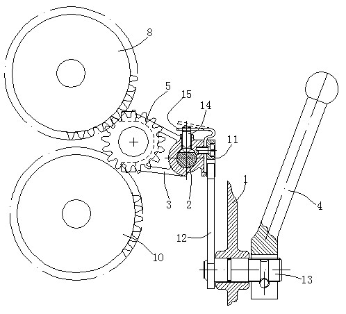
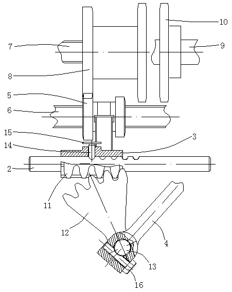
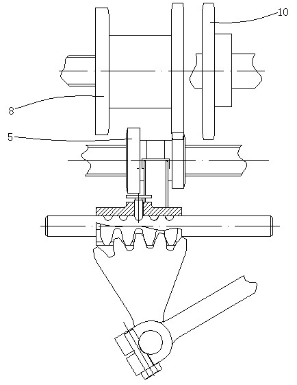
[0022] Such as figure 1 , figure 2 , Figure 5 As shown, a shift shaft 6, a first positioning shaft 7 and a second positioning shaft 9 are rotatably arranged in the transmission box body 1, and these three shafts are parallel to each other. Wherein, the reverse gear 10 is fixedly sleeved on the second positioning shaft 9, the forward gear 8 is fixedly sleeved on the first positioning shaft 7, and the driving gear 5 is slidingly sleeved on the shifting shaft 6, and the driving gear 5 and the forward gear 8 are duplex gears, and driving gear 5, forward gear 8 and reverse gear 10 are all located in transmission box casing 1. A shift fork shaft 2 is fixed in the transmission box body 1, and the shift fork shaft 2 is parallel to the shift shaft 6, and a shift fork 3 is arranged in the transmission case body 1, and the shift fork 3 The bushing is set on the sh...


PUM


Abstract

The invention discloses a gear-shifting device of a mini-tiller. A reverse gear is fixedly sleeved on a second locating shaft, a forward gear is fixedly sleeved on a first locating shaft, and a driving gear is slidingly sleeved on a gear-shifting shaft. A declutch shift shaft is fixed in a transmission case body, a gear-shifting fork is sleeved on the declutch shift shaft, a clamping foot of the gear-shifting fork is jointed with the driving gear in a clamped manner, and the gear-shifting fork can slide on the declutch shift shaft. A teeth row is fixed on the gear-shifting fork, the teeth row is meshed with sector teeth, the sector teeth are fixed with the inner end of a rotating shaft, the rotating shaft is arranged on the transmission case body in a penetrating manner, and the outer end of the rotating shaft is fixed with a control arm. According to the matching of the sector teeth and a fluted disc, the gear-shifting fork is moved by the gear-shifting device, so that one gear-shifting fork and one declutch shift shaft can realize the gear-shifting action, the gear-shifting fork can be effectively located on the declutch shift shaft so as to completely eradicate the phenomenon of putting into wrong gear, the internal structure of the transmission case is simplified, and the production cost of the mini-tiller transmission case is greatly reduced; and the mini-tiller gear-shifting device provided by the invention has the advantages of simple structure, easiness in assembling, good reliability, convenience in operation and the like.

Description

technical field [0001] The invention belongs to the technical field of tillage machines, and in particular relates to a shifting device on a tillage machine. Background technique [0002] Tillers are powered by small diesel engines or gasoline engines. They have the characteristics of light weight, small size, and simple structure. They can be widely used in dry land, paddy fields, orchards, etc. in plains, mountains, and hills. The tiller can be used freely in the field, which is convenient for users to use and store. It saves the trouble that large-scale agricultural machinery cannot enter the fields in mountainous areas. It is the best choice for farmers and consumers to replace cattle farming. [0003] Existing micro tillage machines generally have two forward gears and one reverse gear. The switching between the two forward gears, the high gear and the low gear, and the switching between the forward gear and the reverse gear are each completed by a shift fork. The shif...

Claims


Application Information

Patent Timeline
Patent Type & Authority Applications(China)
IPC IPC(8): F16H63/30
Inventor 陈万荣
Owner 陈万荣
Why Eureka
Try Eureka